Cisco AIR-AP1242AG-E-K9 Hardware Installation Guide - Page 73
Attaching the Access Point to the Mounting Bracket, Securing the Access Point to the Mounting - replacement
 |
View all Cisco AIR-AP1242AG-E-K9 manuals
Add to My Manuals
Save this manual to your list of manuals |
Page 73 highlights
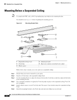
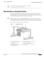
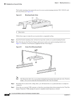
Chapter 6 Mounting Instructions Attaching the Access Point to the Mounting Bracket Step 5 Step 6 Step 7 Step 8 Step 9 Step 10 Step 11 Adjust the height of the T-bar box hanger to provide antenna clearance above the ceiling tile using the height adjusting screws (refer to Figure 6-3). Attach the T-rail clips on each end of the T-bar box hanger to the ceiling grid T-rails. Make sure the clips are securely attached to the T-rails. Connect a drop wire to a building structural element and through the hole provided in the bracket mounting clip. This additional support is required in order to comply with the U.S. National Electrical Safety Code. Attach the access point to the access point mounting bracket (refer to the "Attaching the Access Point to the Mounting Bracket" section. Connect the Ethernet cables to the access point. If you need additional security, you can secure the access point to a nearby immovable object using a Kensington lock and security cable. Verify that the access point is operating before replacing the ceiling tile. Attaching the Access Point to the Mounting Bracket Follow these steps to attach the access point to the mounting bracket: Step 1 Step 2 Step 3 Step 4 Step 5 Step 6 Line up the three mounting pins on the access point with the large ends of the keyhole-shaped holes on the mounting bracket. Insert the access point into the keyhole shaped holes and maintain a slight pressure to hold it in place. Slide the access point's mounting pins into the small ends of the keyhole-shaped holes on the mounting bracket and push the connector end of the access point. You will hear a click when the locking detent contacts the access point and locks it into place. Attach and adjust the antenna(s) or antenna cables. Connect the Ethernet cable to the access point's Ethernet port. If using local power, insert the 1200 series power module cable connector into the access point's 48-VDC power port. Securing the Access Point to the Mounting Bracket The security hasp on the mounting bracket enables you to lock the access point to the bracket to make it more secure. When the access point is properly installed on the mounting bracket, the holes in the security hasps line up so you can install a padlock. Known compatible padlocks are Master Lock models 120T or 121T. OL-4310-05 Cisco Aironet 1200 Series Access Point Hardware Installation Guide 6-7
-
 1
1 -
2
-
3
-
4
-
5
-
6
-
7
-
8
-
9
-
10
-
11
-
12
-
13
-
14
-
15
-
16
-
17
-
18
-
19
-
20
-
21
-
22
-
23
-
24
-
25
-
26
-
27
-
28
-
29
-
30
-
31
-
32
-
33
-
34
-
35
-
36
-
37
-
38
-
39
-
40
-
41
-
42
-
43
-
44
-
45
-
46
-
47
-
48
-
49
-
50
-
51
-
52
-
53
-
54
-
55
-
56
-
57
-
58
-
59
-
60
-
61
-
62
-
63
-
64
-
65
-
66
-
67
-
 68
68 -
 69
69 -
 70
70 -
 71
71 -
 72
72 -
 73
73 -
 74
74 -
 75
75 -
 76
76 -
 77
77 -
 78
78 -
79
-
80
-
81
-
82
-
83
-
84
-
85
-
86
-
87
-
88
-
89
-
90
-
91
-
92
-
93
-
94
-
95
-
96
-
97
-
98
-
99
-
100
-
101
-
102
-
103
-
104
-
105
-
106
-
107
-
108
-
109
-
110
-
111
-
112
-
113
-
114
-
115
-
116
-
117
-
118
-
119
-
120
-
121
-
122
-
123
-
124
-
125
-
126
-
127
-
128
-
129
-
130
-
131
-
132
-
133
-
134
-
135
-
136
-
137
-
138
-
139
-
140
-
141
-
142
-
143
-
144
-
145
-
146
-
147
-
148
-
149
-
150
-
151
-
152
-
153
-
154
-
155
-
156
-
157
-
158
-
159
-
160
 |
 |