Cisco AIR-AP1242AG-E-K9 Hardware Installation Guide - Page 77
Opening the Access Cover
 |
View all Cisco AIR-AP1242AG-E-K9 manuals
Add to My Manuals
Save this manual to your list of manuals |
Page 77 highlights
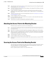
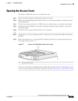
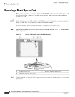
Chapter 7 2.4-GHz Radio Upgrade Opening the Access Cover Opening the Access Cover To open the 2.4-GHz radio access cover, follow these steps: Step 1 Step 2 Step 3 Step 4 Step 5 Remove all cables and power connections from the access point. Remove all static-generating items from the work area, such as plastic material, styrofoam cups, and other similar items. Place the access point and the new 2.4-GHz radio (in its antistatic bag) on an antistatic work surface. Discharge any static buildup on your body by touching a grounded surface (antistatic work surface) before proceeding. Position the access point so that the bottom cover is facing up. Caution The internal access point components and the 2.4-GHz radio can be damaged by ESD from improper handling. Step 6 Remove the bottom access cover using the T-10 tamper-resistant Torx L-wrench provided with your Cisco radio card (see Figure 7-1). Figure 7-1 Location of 2.4-GHz Radio Access Cover Screw 1 74458 1 Access Cover Screw If your access point was not configured with a 2.4-GHz radio, go to the "Removing a Blank Spacer Card" section. If you are replacing an existing 2.4-GHz radio, go to the "Removing a 2.4-GHz Radio" section. OL-4310-05 Cisco Aironet 1200 Series Access Point Hardware Installation Guide 7-3
-
 1
1 -
2
-
3
-
4
-
5
-
6
-
7
-
8
-
9
-
10
-
11
-
12
-
13
-
14
-
15
-
16
-
17
-
18
-
19
-
20
-
21
-
22
-
23
-
24
-
25
-
26
-
27
-
28
-
29
-
30
-
31
-
32
-
33
-
34
-
35
-
36
-
37
-
38
-
39
-
40
-
41
-
42
-
43
-
44
-
45
-
46
-
47
-
48
-
49
-
50
-
51
-
52
-
53
-
54
-
55
-
56
-
57
-
58
-
59
-
60
-
61
-
62
-
63
-
64
-
65
-
66
-
67
-
68
-
69
-
70
-
71
-
 72
72 -
 73
73 -
 74
74 -
 75
75 -
 76
76 -
 77
77 -
 78
78 -
 79
79 -
 80
80 -
 81
81 -
 82
82 -
83
-
84
-
85
-
86
-
87
-
88
-
89
-
90
-
91
-
92
-
93
-
94
-
95
-
96
-
97
-
98
-
99
-
100
-
101
-
102
-
103
-
104
-
105
-
106
-
107
-
108
-
109
-
110
-
111
-
112
-
113
-
114
-
115
-
116
-
117
-
118
-
119
-
120
-
121
-
122
-
123
-
124
-
125
-
126
-
127
-
128
-
129
-
130
-
131
-
132
-
133
-
134
-
135
-
136
-
137
-
138
-
139
-
140
-
141
-
142
-
143
-
144
-
145
-
146
-
147
-
148
-
149
-
150
-
151
-
152
-
153
-
154
-
155
-
156
-
157
-
158
-
159
-
160
 |
 |