Cisco AIR-AP1242AG-E-K9 Hardware Installation Guide - Page 81
Installing a 2.4-GHz Radio
 |
View all Cisco AIR-AP1242AG-E-K9 manuals
Add to My Manuals
Save this manual to your list of manuals |
Page 81 highlights
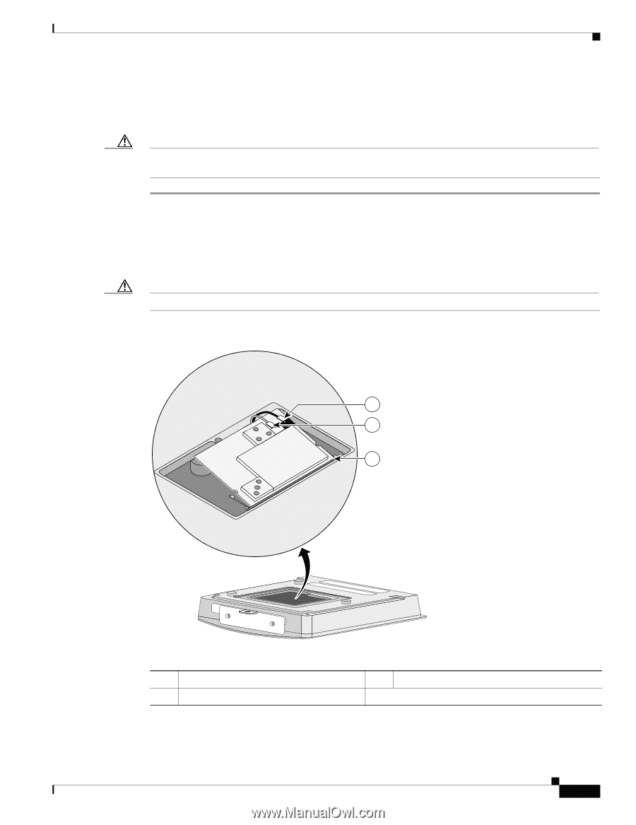
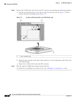
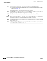
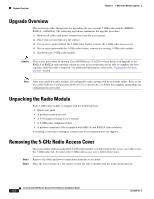
Chapter 7 2.4-GHz Radio Upgrade Installing a 2.4-GHz Radio Installing a 2.4-GHz Radio To install a new 2.4-GHz radio card into the access point, follow these steps: Caution The internal access point components and the 2.4-GHz radio can be damaged by ESD from improper handling. Step 1 Step 2 Step 3 Carefully remove the Cisco Aironet 2.4-GHz radio card from its anti-static bag. Grasp the radio card only on the edges, being careful not to touch components on the board or the gold connector pins. Connect the black antenna wire connector to the radio card antenna connector marked by the black label (see Figure 7-4). Caution To avoid damaging the antenna wire assemblies, handle them by their connectors. Figure 7-4 Antenna Connector Labels and Mini-PCI Connector 1 MAIN AUX 2 3 74251 1 Antenna connector (black wire) 2 Antenna connector (white wire) 3 Mini-PCI connector Step 4 Connect the white antenna wire connector to the radio card antenna connector marked by the white label (see Figure 7-4). OL-4310-05 Cisco Aironet 1200 Series Access Point Hardware Installation Guide 7-7
-
 1
1 -
2
-
3
-
4
-
5
-
6
-
7
-
8
-
9
-
10
-
11
-
12
-
13
-
14
-
15
-
16
-
17
-
18
-
19
-
20
-
21
-
22
-
23
-
24
-
25
-
26
-
27
-
28
-
29
-
30
-
31
-
32
-
33
-
34
-
35
-
36
-
37
-
38
-
39
-
40
-
41
-
42
-
43
-
44
-
45
-
46
-
47
-
48
-
49
-
50
-
51
-
52
-
53
-
54
-
55
-
56
-
57
-
58
-
59
-
60
-
61
-
62
-
63
-
64
-
65
-
66
-
67
-
68
-
69
-
70
-
71
-
72
-
73
-
74
-
75
-
 76
76 -
 77
77 -
 78
78 -
 79
79 -
 80
80 -
 81
81 -
 82
82 -
 83
83 -
 84
84 -
 85
85 -
 86
86 -
87
-
88
-
89
-
90
-
91
-
92
-
93
-
94
-
95
-
96
-
97
-
98
-
99
-
100
-
101
-
102
-
103
-
104
-
105
-
106
-
107
-
108
-
109
-
110
-
111
-
112
-
113
-
114
-
115
-
116
-
117
-
118
-
119
-
120
-
121
-
122
-
123
-
124
-
125
-
126
-
127
-
128
-
129
-
130
-
131
-
132
-
133
-
134
-
135
-
136
-
137
-
138
-
139
-
140
-
141
-
142
-
143
-
144
-
145
-
146
-
147
-
148
-
149
-
150
-
151
-
152
-
153
-
154
-
155
-
156
-
157
-
158
-
159
-
160
 |
 |