Cisco AIR-BR350-A-K9 Hardware Installation Guide
Cisco AIR-BR350-A-K9 - Aironet 350 Wireless Bridge Manual
 |
UPC - 746320634890
View all Cisco AIR-BR350-A-K9 manuals
Add to My Manuals
Save this manual to your list of manuals |
Cisco AIR-BR350-A-K9 manual content summary:
- Cisco AIR-BR350-A-K9 | Hardware Installation Guide - Page 1
Cisco Aironet 350 Series Bridge Hardware Installation Guide Corporate Headquarters Cisco Systems, Inc. 170 West Tasman Drive San Jose, CA 95134-1706 USA http://www.cisco.com Tel: 408 526-4000 800 553-NETS (6387) Fax: 408 526-4100 Text Part Number: OL-0658-01 - Cisco AIR-BR350-A-K9 | Hardware Installation Guide - Page 2
document or Website are the property of their respective owners. The use of the word partner does not imply a partnership relationship between Cisco and any other company. (0406R) Cisco Aironet 350 Series Bridge Hardware Installation Guide Copyright ©2004 Cisco Systems, Inc. All rights reserved. - Cisco AIR-BR350-A-K9 | Hardware Installation Guide - Page 3
Unit That Extends Wireless Range 1-5 Bridge Operating as a Root Access Point 1-6 Bridge Specifications 1-7 Installation 2-1 Cautions and Warnings 2-2 Installation Guidelines 2-3 Basic Guidelines 2-3 Antenna Options 2-3 CONTENTS Cisco Aironet 350 Series Bridge Hardware Installation Guide iii - Cisco AIR-BR350-A-K9 | Hardware Installation Guide - Page 4
Bridge's IP Address 3-3 Setting the Bridge's IP Address and SSID 3-4 Entering Basic Settings 3-4 Using an Internet Browser 3-5 Using the Command-Line Interface 3-8 Default Basic Settings 3-16 Troubleshooting Compliance Statement B-3 Cisco Aironet 350 Series Bridge Hardware Installation Guide iv OL- - Cisco AIR-BR350-A-K9 | Hardware Installation Guide - Page 5
for European Union Countries B-6 Antenna Basics C-1 Antenna System C-2 General Antenna and Safety Tips C-3 Lightning Arrestors C-3 Antenna Cable C-4 Antenna Types C-4 Basic Antenna Alignment C-5 Performing a Link Test C-6 OL-1412-01 Cisco Aironet 350 Series Bridge Hardware Installation Guide v - Cisco AIR-BR350-A-K9 | Hardware Installation Guide - Page 6
Contents Cisco Aironet 350 Series Bridge Hardware Installation Guide vi OL-1412-01 - Cisco AIR-BR350-A-K9 | Hardware Installation Guide - Page 7
of the Cisco Aironet 350 Series Bridge Hardware Installation Guide. Objectives This publication explains the steps for initial setup and configuration of the Cisco Aironet 350 Series Bridge (here after referred to as the bridge). This publication also provides troubleshooting information and - Cisco AIR-BR350-A-K9 | Hardware Installation Guide - Page 8
. Notes contain helpful suggestions or references to materials not contained in this manual. Caution Means reader be careful. In this situation, you might do something that could result in equipment damage or loss of data. Cisco Aironet 350 Series Bridge Hardware Installation Guide viii OL-1412-01 - Cisco AIR-BR350-A-K9 | Hardware Installation Guide - Page 9
card client adapters. • Cisco Aironet Wireless LAN Adapters Software Configuration Guide provides instructions for installing and using the wireless client adapter utilities. • Mounting Instructions for the Cisco Aironet 350 Series Bridges. Obtaining Documentation Cisco documentation and additional - Cisco AIR-BR350-A-K9 | Hardware Installation Guide - Page 10
the tools on the Cisco TAC website requires a Cisco.com user ID and password. If you have a valid service contract but do not have a login ID or password, register at this URL: http://tools.cisco.com/RPF/register/register.do Cisco Aironet 350 Series Bridge Hardware Installation Guide x OL-1412-01 - Cisco AIR-BR350-A-K9 | Hardware Installation Guide - Page 11
The Cisco Product Catalog describes the networking products offered by Cisco Systems, as well as ordering and customer support services. Access the Cisco Product Catalog at this URL: http://cisco.com/univercd/cc/td/doc/pcat/ OL-1412-01 Cisco Aironet 350 Series Bridge Hardware Installation Guide xi - Cisco AIR-BR350-A-K9 | Hardware Installation Guide - Page 12
Protocol Journal at this URL: http://www.cisco.com/ipj • Training-Cisco offers world-class networking training. Current offerings in network training are listed at this URL: http://www.cisco.com/en/US/learning/index.html Cisco Aironet 350 Series Bridge Hardware Installation Guide xii OL-1412-01 - Cisco AIR-BR350-A-K9 | Hardware Installation Guide - Page 13
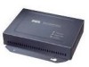
Overview CH A P T E R 1 Cisco Aironet 350 Series Bridges are wireless LAN transceivers that connect two or more remote networks into a single LAN. The bridge can also be used as a rugged access point, providing network access to wireless client devices. The bridge uses a browser-based management - Cisco AIR-BR350-A-K9 | Hardware Installation Guide - Page 14
, such as the Cisco Catalyst Inline Power Patch Panel Note Cisco Aironet 340 series bridges rely on a separate power supply plugged into the power port on the back of the bridge. Caution Cisco Aironet power injectors are designed for use with 350 series access points and bridges only. Using the - Cisco AIR-BR350-A-K9 | Hardware Installation Guide - Page 15
Figure 1-1. Figure 1-1 Indicator Lights on the Bridge CISCO AIRONET 350 SERIES WIRELESS BRIDGE ETHERNET ACTIVITY ASSOCIATION STATUS RADIO ACTIVITY Ethernet Status is received or transmitted over the bridge's radio. OL-1412-01 Cisco Aironet 350 Series Bridge Hardware Installation Guide 1-3 - Cisco AIR-BR350-A-K9 | Hardware Installation Guide - Page 16
LEFT SERIAL PORT ONLINE POWER ETHERNET RIGHT/PRIMARY Bridge (non-root) W bridges over the wireless link. Data packets sent from Workstation A to the file server go through the wired LAN segment and do not go across the wireless link. Cisco Aironet 350 Series Bridge Hardware Installation Guide - Cisco AIR-BR350-A-K9 | Hardware Installation Guide - Page 17
the range of wireless clients from the main root LAN. When you configure a bridge as a repeater access point, the Spanning-Tree Protocol is deactivated. If you use a bridge as a repeater, the data throughput is cut in half. OL-1412-01 Cisco Aironet 350 Series Bridge Hardware Installation Guide 1-5 - Cisco AIR-BR350-A-K9 | Hardware Installation Guide - Page 18
A W I RCEILSECSOS AAICRCOE SN SETP 3O I50N STERIES RADIOAASCSTIOVCIEITTAYTHIEORNNSETTATAUCSTIVITY LEFT SERIAL PORT ONLINE POWER ETHERNET RIGHT/PRIMARY Bridge (root unit) 53090 Workstation Laptop Workstation Cisco Aironet 350 Series Bridge Hardware Installation Guide 1-6 OL-1412-01 - Cisco AIR-BR350-A-K9 | Hardware Installation Guide - Page 19
Class B, EN 50082-1, UL1950, CSA 22.2 No. 950, EN 60950, IEC 60950, VCCI, and others (see Appendix B). 350 series bridge complies with UL 2043 for products installed in air handling spaces, such as above suspended ceilings. OL-1412-01 Cisco Aironet 350 Series Bridge Hardware Installation Guide 1-7 - Cisco AIR-BR350-A-K9 | Hardware Installation Guide - Page 20
Bridge Specifications Chapter 1 Overview Cisco Aironet 350 Series Bridge Hardware Installation Guide 1-8 OL-1412-01 - Cisco AIR-BR350-A-K9 | Hardware Installation Guide - Page 21
2 This chapter describes the setup of the bridge and includes the following sections: • Cautions and Warnings • Installation Guidelines • Unpacking the Bridge • Connecting the Antenna Cable • Connecting the Ethernet Cables OL-1412-01 Cisco Aironet 350 Series Bridge Hardware Installation Guide 2-1 - Cisco AIR-BR350-A-K9 | Hardware Installation Guide - Page 22
only. Using the power injector with other Ethernet-ready devices can damage the equipment. Caution The operational voltage range for Cisco Aironet 350 series access points and bridges is 24 to 60 VDC. Higher voltage can damage the equipment. Warning Do not operate your wireless network device near - Cisco AIR-BR350-A-K9 | Hardware Installation Guide - Page 23
- A physical obstruction such as a building or a tree can block or hinder communication between bridges. Avoid locating the antennas in a location where there is an obstruction between the sending and receiving antennas. OL-1412-01 Cisco Aironet 350 Series Bridge Hardware Installation Guide 2-3 - Cisco AIR-BR350-A-K9 | Hardware Installation Guide - Page 24
the building material used in construction. For example, drywall construction allows greater range than concrete blocks. Metal or steel construction is a barrier to radio signals. Cisco Aironet 350 Series Bridge Hardware Installation Guide 2-4 OL-1412-01 - Cisco AIR-BR350-A-K9 | Hardware Installation Guide - Page 25
Start Guide: Cisco Aironet 350 Series Bridge • Cisco Aironet Series Wireless Access Points and Bridges CD-ROM • Cisco Information Packet, which contains warranty, safety, and support information • Cisco Aironet 350 Series Power Injector and accessory kit • Power injector • Power cord • Straight - Cisco AIR-BR350-A-K9 | Hardware Installation Guide - Page 26
cable.The 350 series bridge power options include: • A switch with inline power, such as a Cisco Catalyst 3524-PWR-XL • An inline power patch panel, such as a Cisco Catalyst Inline Power Patch Panel • A Cisco Aironet power injector Cisco Aironet 350 Series Bridge Hardware Installation Guide 2-6 OL - Cisco AIR-BR350-A-K9 | Hardware Installation Guide - Page 27
RADIOAASCSTIOVCIEITTAYTHIEORNNSETTATAUCSTIVITY LEFT SERIAL PORT ONLINE POWER ETHERNET RIGHT/PRIMARY Bridge Power cord Universal power supply Caution Cisco Aironet power injectors are designed for use with 350 series access points and bridges only. Using the power injector with other Ethernet - Cisco AIR-BR350-A-K9 | Hardware Installation Guide - Page 28
minutes to complete. During normal operation, the LEDs blink green. Refer to Chapter 4, "Troubleshooting," for LED descriptions. Follow the steps in Chapter 3, "Basic Configuration," to assign basic settings to the bridge. Cisco Aironet 350 Series Bridge Hardware Installation Guide 2-8 OL-1412-01 - Cisco AIR-BR350-A-K9 | Hardware Installation Guide - Page 29
or a Telnet session, or a Simple Network Management Protocol (SNMP) application. Consult Chapter 2 in the Cisco Aironet 350 Series Bridge Software Configuration Guide for SNMP instructions and for complete descriptions of these interfaces. This chapter includes the following sections: • Before You - Cisco AIR-BR350-A-K9 | Hardware Installation Guide - Page 30
instructions on setting up security, filtering, and other bridge features, consult the Cisco Aironet 350 Series Bridge Software Configuration Guide on the bridge CD. Follow these steps to enter the basic bridge settings: 1. Connect the bridge as described in the Quick Start Guide: Cisco Aironet 350 - Cisco AIR-BR350-A-K9 | Hardware Installation Guide - Page 31
browser to access the Cisco Software Center at the following URL: http://www.cisco.com/public/sw-center/sw-wireless.shtml Locate the bridge utilities section and click 3 of the Cisco Aironet 350 Series Bridge Software Configuration Guide. To check the IP address, browse to the bridge's browser-based - Cisco AIR-BR350-A-K9 | Hardware Installation Guide - Page 32
using your Internet browser, the bridge's serial port, or a Telnet session. Note Consult Chapter 2 in the Cisco Aironet 350 Series Bridge Software Configuration Guide for instructions on using SNMP to configure the bridge. Cisco Aironet 350 Series Bridge Hardware Installation Guide 3-4 OL-1412-01 - Cisco AIR-BR350-A-K9 | Hardware Installation Guide - Page 33
on the Express Setup page (see Figure 3-1). Note The bridge is compatible with Microsoft Internet Explorer versions 4.0 or later and Netscape Communicator versions 4.0 or later. Figure 3-1 The Express Setup Page OL-1412-01 Cisco Aironet 350 Series Bridge Hardware Installation Guide 3-5 - Cisco AIR-BR350-A-K9 | Hardware Installation Guide - Page 34
to associate with the bridge. The SSID can be any alphanumeric entry from 2 to 32 characters long. Select a network role for the bridge from the Role in Radio Network pull-down menu. The menu contains the following options: Cisco Aironet 350 Series Bridge Hardware Installation Guide 3-6 OL-1412-01 - Cisco AIR-BR350-A-K9 | Hardware Installation Guide - Page 35
if your network contains Cisco Aironet devices that operate at 2 Mbps. • non-Aironet 802.11-Select this setting if the bridge is operating as an access point and there are non-Cisco Aironet devices on your wireless LAN. OL-1412-01 Cisco Aironet 350 Series Bridge Hardware Installation Guide 3-7 - Cisco AIR-BR350-A-K9 | Hardware Installation Guide - Page 36
"Security Setup" section in Chapter 3 of the Cisco Aironet 350 Series Bridge Software Configuration Guide describes User Management. Click OK. The Setup page your bridge through a terminal emulation program or a Telnet session instead of through your browser. This section provides instructions for - Cisco AIR-BR350-A-K9 | Hardware Installation Guide - Page 37
, male-to-female, straight-through serial cable (provided with your bridge) to the COM port on a computer and to the RS-232 serial port on the back of the bridge. Figure 3-3 shows the location of the bridge's serial port. OL-1412-01 Cisco Aironet 350 Series Bridge Hardware Installation Guide 3-9 - Cisco AIR-BR350-A-K9 | Hardware Installation Guide - Page 38
STERIES RADIOAASCSTIOVCIEITTAYTHIEORNNSETTATAUCSTIVITY 5VDC SERIAL PORT LEFT SERIAL PORT ONLINE POWER ETHERNET RIGHT/PRIMARY Step 2 Open the terminal emulator. RS-232 9-pin serial extension cable to PC COM port 3-10 Cisco Aironet 350 Series Bridge Hardware Installation Guide OL-1412-01 - Cisco AIR-BR350-A-K9 | Hardware Installation Guide - Page 39
Service Set ID (SSID). Enter an SSID for the bridge. The SSID is a unique identifier that client devices use to associate with the bridge. The SSID can be any alphanumeric entry from 2 to 32 characters long. Press Enter when you have completed your entry. OL-1412-01 Cisco Aironet 350 Series Bridge - Cisco AIR-BR350-A-K9 | Hardware Installation Guide - Page 40
to select this setting. The bridge will use the settings you enter on the Root Radio Hardware page. Chapter 3 of the Cisco Aironet 350 Series Bridge Software Configuration Guide describes the Root Radio Hardware page. 3-12 Cisco Aironet 350 Series Bridge Hardware Installation Guide OL-1412-01 - Cisco AIR-BR350-A-K9 | Hardware Installation Guide - Page 41
3 of the Cisco Aironet 350 Series Bridge Software Configuration Guide describes User Management. Press ap and press Enter to apply your basic settings. If you changed the Role in Radio Network setting, your bridge reboots. Using a Telnet Session This section provides instructions for using a Telnet - Cisco AIR-BR350-A-K9 | Hardware Installation Guide - Page 42
setting is used when you want to manually assign a static IP address to your bridge or your network does not have a working bridge. When you select Root Access Point, the bridge's Spanning-Tree Protocol (STP) function is disabled. 3-14 Cisco Aironet 350 Series Bridge Hardware Installation Guide - Cisco AIR-BR350-A-K9 | Hardware Installation Guide - Page 43
Radio Hardware page. Chapter 3 of the Cisco Aironet 350 Series Bridge Software Configuration Guide describes the Root Radio Hardware page. Use the Ensure Compatibility With setting to automatically configure the bridge to be compatible with other devices on your wireless LAN: • 2Mb/sec clients-Press - Cisco AIR-BR350-A-K9 | Hardware Installation Guide - Page 44
Security Setup" section in Chapter 3 of the Cisco Aironet 350 Series Bridge Software Configuration Guide describes User Management. Press ap and press Enter the bridge's Express Setup page. Table 3-2 Default Settings on the Express Setup Page Setting Name Default Value System Name AIR- - Cisco AIR-BR350-A-K9 | Hardware Installation Guide - Page 45
the Cisco TAC website at http://www.cisco.com/tac. Select Wireless LAN under Top Issues. Sections in this chapter include: • Checking the Top Panel Indicators • Checking Basic Settings • Resetting to the Default Configuration OL-1412-01 Cisco Aironet 350 Series Bridge Hardware Installation Guide - Cisco AIR-BR350-A-K9 | Hardware Installation Guide - Page 46
At least one wireless client device is associated with the unit. Not associated with a wireless device. Check the device SSID and WEP encryption key settings. Verify that all wireless devices have identical settings. Cisco Aironet 350 Series Bridge Hardware Installation Guide 4-2 OL-1412-01 - Cisco AIR-BR350-A-K9 | Hardware Installation Guide - Page 47
3 on your wireless LAN adapter to 0987654321 and select it as the transmit key, you must also set WEP Key 3 on the bridge to exactly the same value. Refer to the "Security Setup" section in Chapter 3 of the Cisco Aironet 350 Series Bridge Software Configuration Guide for instructions on setting the - Cisco AIR-BR350-A-K9 | Hardware Installation Guide - Page 48
may prevent communications with close devices or devices on the edge of the radiation pattern. Typically, high-gain antennas compress the radiation pattern in some directions to increase the gain in other directions. Cisco Aironet 350 Series Bridge Hardware Installation Guide 4-4 OL-1412-01 - Cisco AIR-BR350-A-K9 | Hardware Installation Guide - Page 49
the Cisco Aironet 350 Series Bridge Software Configuration Guide for more port on the bridge. Open a terminal-emulation program on your computer. Note These instructions describe HyperTeminal; other the bridge by unplugging the power connector and then plugging it back in. When the bridge reboots - Cisco AIR-BR350-A-K9 | Hardware Installation Guide - Page 50
Resetting to the Default Configuration Chapter 4 Troubleshooting Cisco Aironet 350 Series Bridge Hardware Installation Guide 4-6 OL-1412-01 - Cisco AIR-BR350-A-K9 | Hardware Installation Guide - Page 51
A A P P E N D I X Translated Safety Warnings This appendix provides translations of the safety warnings that appear in this publication. These translated warnings apply to other documents in which they appear in English. OL-1412-01 Cisco Aironet 350 Series Bridge Hardware Installation Guide A-7 - Cisco AIR-BR350-A-K9 | Hardware Installation Guide - Page 52
Warnings Explosive Device Proximity Warning Warning Do not operate your wireless network device near unshielded blasting caps or in an explosive inte enheten modifierats för att kunna användas i sådana sammanhang. Cisco Aironet 350 Series Bridge Hardware Installation Guide A-8 OL-1412-01 - Cisco AIR-BR350-A-K9 | Hardware Installation Guide - Page 53
its power source. Waarschuwing Raadpleeg de installatie-aanwijzingen voordat u het systeem met de voeding verbindt. Varoitus Lue asennusohjeet ennen järjestelmän yhdistämistä virtalähteeseen. Lightning Activity Warning OL-1412-01 Cisco Aironet 350 Series Bridge Hardware Installation Guide A-9 - Cisco AIR-BR350-A-K9 | Hardware Installation Guide - Page 54
10 ampeerin sulaketta tai suojakytkintä. Attention Pour ce qui est de la protection contre les courts-circuits (surtension), ce produit dépend de l'installation é les conducteurs de phase (conducteurs de charge). A-10 Cisco Aironet 350 Series Bridge Hardware Installation Guide OL-1412-01 - Cisco AIR-BR350-A-K9 | Hardware Installation Guide - Page 55
eller överspänningsskydd används på fasledarna (samtliga strömförande ledare) för internationellt bruk max. 240 V växelström, 10 A (i USA max. 120 V växelström, 15 A). OL-1412-01 Cisco Aironet 350 Series Bridge Hardware Installation Guide A-11 - Cisco AIR-BR350-A-K9 | Hardware Installation Guide - Page 56
un'accurata installazione e sistemazione al suolo dell'antenna, fare riferimento ai codici nazionali e locali (es. U.S.A.: NFPA 70, Codice Elettrico Nazionale, Articolo 810, Canada: Codice Elettrico Canadese, Sezione 54). A-12 Cisco Aironet 350 Series Bridge Hardware Installation Guide OL-1412-01 - Cisco AIR-BR350-A-K9 | Hardware Installation Guide - Page 57
antennen, undersök landets and den lokala omgivningens koder (t.ex. U.S.: NFPA 70, National Electrical Code, Article 810, Canada: Canadian Electrical Code, Section 54). OL-1412-01 Cisco Aironet 350 Series Bridge Hardware Installation Guide A-13 - Cisco AIR-BR350-A-K9 | Hardware Installation Guide - Page 58
Installation and Grounding Warning Appendix A Translated Safety Warnings A-14 Cisco Aironet 350 Series Bridge Hardware Installation Guide OL-1412-01 - Cisco AIR-BR350-A-K9 | Hardware Installation Guide - Page 59
Community, Switzerland, Norway, Iceland, and Liechtenstein • Declaration of Conformity for RF Exposure • Guidelines for Operating Cisco Aironet Access Points and Bridges in Japan • Declaration of Conformity Statements OL-1412-01 Cisco Aironet 350 Series Bridge Hardware Installation Guide B-1 - Cisco AIR-BR350-A-K9 | Hardware Installation Guide - Page 60
AIR-BR351, AIR-BR352 FCC Certification number: LDK102040 (AIR-BR35x) Manufacturer: Cisco provide reasonable protection against instructions the receiving antenna. • Increase Cisco could void the user's authority to operate this device. Cisco Aironet 350 Series Bridge Hardware Installation Guide - Cisco AIR-BR350-A-K9 | Hardware Installation Guide - Page 61
aux autres dispositions pertinantes de la Directive 1999/5/EC. Þessi búnaður samrýmist lögboðnum kröfum og öðrum ákvæðum tilskipunar 1999/5/ESB. Cisco Aironet 350 Series Bridge Hardware Installation Guide B-3 - Cisco AIR-BR350-A-K9 | Hardware Installation Guide - Page 62
countries that have adopted the European R&TTE directive 1999/5/EC and/or the CEPT recommendation Rec 70.03. For more details on legal combinations of power levels and antennas, contact Cisco Corporate Compliance. Cisco Aironet 350 Series Bridge Hardware Installation Guide B-4 OL-1412-01 - Cisco AIR-BR350-A-K9 | Hardware Installation Guide - Page 63
recommendations on avoiding radio interference, such as setting partitions. 3. If this equipment causes RF interference to a specified low-power radio station of RF-ID, contact the number below. Contact Number: 03-5549-6500 OL-1412-01 Cisco Aironet 350 Series Bridge Hardware Installation Guide B-5 - Cisco AIR-BR350-A-K9 | Hardware Installation Guide - Page 64
: http://www.ciscofax.com Declaration of Conformity Statement for European Union Countries The Declaration of Conformity statement for the European Union countries is listed below: Cisco Aironet 350 Series Bridge Hardware Installation Guide B-6 OL-1412-01 - Cisco AIR-BR350-A-K9 | Hardware Installation Guide - Page 65
Cisco Systems Inc. 170 West Tasman Drive San Jose, CA 95134 - USA Declare under our sole responsibility that the product, AIR-BR350 / 2.4 GHz DS 11 Mbps Ethernet Wireless Bridge Variants : AIR-BR350-E-K9, AIR-SSB350-E-K9, AIR-BR351, AIR Cisco Aironet 350 Series Bridge Hardware Installation Guide B-7 - Cisco AIR-BR350-A-K9 | Hardware Installation Guide - Page 66
Declaration of Conformity Statements Appendix B Declarations of Conformity and Regulatory Information Cisco Aironet 350 Series Bridge Hardware Installation Guide B-8 OL-1412-01 - Cisco AIR-BR350-A-K9 | Hardware Installation Guide - Page 67
with various gain ratings. This appendix provides basic antenna information. The following topics are covered in this section: Antenna System General Antenna and Safety Tips Lightning Arrestors Antenna Cable Antenna Types OL-1412-01 Cisco Aironet 350 Series Bridge Hardware Installation Guide C-1 - Cisco AIR-BR350-A-K9 | Hardware Installation Guide - Page 68
and hills must be considered. Distance is a primary factor when using bridge-to-bridge communications; however, coverage area also becomes important when you are using wireless client devices to communicate with the bridge. Cisco Aironet 350 Series Bridge Hardware Installation Guide C-2 OL-1412-01 - Cisco AIR-BR350-A-K9 | Hardware Installation Guide - Page 69
wireless LAN device near a good source of ground, such as structural steel or the ground on an electrical panel, and ground the arrestor using one of those grounds. Figure 1 shows the connectors on the arrestor and the proper placement of the ground lug. OL-1412-01 Cisco Aironet 350 Series Bridge - Cisco AIR-BR350-A-K9 | Hardware Installation Guide - Page 70
a stronger radiation pattern in a specific direction by focusing the radiation energy to provide a greater coverage distance. Directional antennas include the Yagi antenna, the patch antenna, and the parabolic dish antenna. Cisco Aironet 350 Series Bridge Hardware Installation Guide C-4 OL-1412-01 - Cisco AIR-BR350-A-K9 | Hardware Installation Guide - Page 71
then on the pop-up message click OK to update the selections. e. On the bridge Setup screen, click Associations to view the Association Table screen and verify that the destination bridge is listed in the Association Table. OL-1412-01 Cisco Aironet 350 Series Bridge Hardware Installation Guide C-5 - Cisco AIR-BR350-A-K9 | Hardware Installation Guide - Page 72
the antennas bridge. Enter 1000 in the Link Test Count entry box to increase the number of packets used. Click Link Test to begin the link test operation. When the link test completes, the results are displayed on a pop-up status screen. Cisco Aironet 350 Series Bridge Hardware Installation Guide - Cisco AIR-BR350-A-K9 | Hardware Installation Guide - Page 73
audience vii B basic settings 3-4, 3-16, 4-3 BOOTP 3-6 C cables antenna 2-6, C-4 Ethernet 2-6 serial 3-10 Caution viii cautions 2-2 CLI, common functions Setup page 3-16 G guidelines, installation 2-3 H hardware installation guide Cisco Aironet 350 Series Bridge Hardware Installation Guide IN-1 - Cisco AIR-BR350-A-K9 | Hardware Installation Guide - Page 74
viii safety warnings circuit breaker (15A) warning 10 explosive device proximity warning 8 installation warning 9 lightning activity warning 9 power injector warning 12 serial cable, connecting 3-10 site surveys 2-3 IN-2 Cisco Aironet 350 Series Bridge Hardware Installation Guide OL-1412-01 - Cisco AIR-BR350-A-K9 | Hardware Installation Guide - Page 75
viii troubleshooting basic settings 4-3 indicator lights 4-2 out of range 4-4 reset to defaults 4-5 U unpacking the bridge 2-5 V voltage range 1-7 W warnings 2-2 OL-1412-01 Index web site Cisco Software Center 3-3 weight 1-7 WEP key 4-3 Cisco Aironet 350 Series Bridge Hardware Installation Guide - Cisco AIR-BR350-A-K9 | Hardware Installation Guide - Page 76
Index IN-4 Cisco Aironet 350 Series Bridge Hardware Installation Guide OL-1412-01
-
 1
1 -
 2
2 -
 3
3 -
 4
4 -
 5
5 -
 6
6 -
 7
7 -
8
-
9
-
10
-
11
-
12
-
13
-
14
-
15
-
16
-
17
-
18
-
19
-
20
-
21
-
22
-
23
-
24
-
25
-
26
-
27
-
28
-
29
-
30
-
31
-
32
-
33
-
34
-
35
-
36
-
37
-
38
-
39
-
40
-
41
-
42
-
43
-
44
-
45
-
46
-
47
-
48
-
49
-
50
-
51
-
52
-
53
-
54
-
55
-
56
-
57
-
58
-
59
-
60
-
61
-
62
-
63
-
64
-
65
-
66
-
67
-
68
-
69
-
70
-
71
-
72
-
73
-
74
-
75
-
76
 |
 |

Corporate Headquarters
Cisco Systems, Inc.
170 West Tasman Drive
San Jose, CA 95134-1706
USA
Tel: 408 526-4000
800 553-NETS (6387)
Fax: 408 526-4100
Cisco Aironet 350 Series Bridge Hardware
Installation Guide
Text Part Number: OL-0658-01