Cisco AIR-LAP1131G-A-K9 Hardware Installation Guide - Page 55
Step 7, Caution, Inserting Antenna Card
 |
View all Cisco AIR-LAP1131G-A-K9 manuals
Add to My Manuals
Save this manual to your list of manuals |
Page 55 highlights
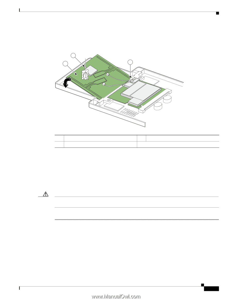
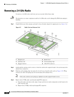
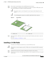
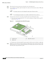
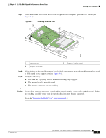
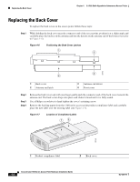
Chapter 4 2.4-GHz Radio Upgrade for Autonomous Access Points Installing a 2.4-GHz Radio Step 7 Insert the antenna card into the notch in the support bracket and gently push until it is seated (see Figure 4-5). Figure 4-5 Inserting Antenna Card 2 1 3 95754 1 Antenna card 2 Support post hole 3 Support bracket notch Step 8 Step 9 Align the hole on the top of the antenna board with the support post and gently push down until the board is fully seated on the support post (see Figure 4-5). Verify the following: a. The radio car is properly secured with both retaining clips engaged. b. The antenna board is properly seated. c. The antenna connectors are not touching. Caution Do not allow antenna connectors to touch while power is applied, or the radio can be damaged. If they are touching, carefully rotate them in opposite directions until they are separated. Go to the "Replacing the Back Cover" section on page 4-8. OL-4309-07 Cisco Aironet 1100 Series Access Point Hardware Installation Guide 4-7
-
 1
1 -
2
-
3
-
4
-
5
-
6
-
7
-
8
-
9
-
10
-
11
-
12
-
13
-
14
-
15
-
16
-
17
-
18
-
19
-
20
-
21
-
22
-
23
-
24
-
25
-
26
-
27
-
28
-
29
-
30
-
31
-
32
-
33
-
34
-
35
-
36
-
37
-
38
-
39
-
40
-
41
-
42
-
43
-
44
-
45
-
46
-
47
-
48
-
49
-
 50
50 -
 51
51 -
 52
52 -
 53
53 -
 54
54 -
 55
55 -
 56
56 -
 57
57 -
 58
58 -
 59
59 -
 60
60 -
61
-
62
-
63
-
64
-
65
-
66
-
67
-
68
-
69
-
70
-
71
-
72
-
73
-
74
-
75
-
76
-
77
-
78
-
79
-
80
-
81
-
82
-
83
-
84
-
85
-
86
-
87
-
88
-
89
-
90
-
91
-
92
-
93
-
94
-
95
-
96
-
97
-
98
-
99
-
100
-
101
-
102
-
103
-
104
-
105
-
106
-
107
-
108
-
109
-
110
-
111
-
112
-
113
-
114
-
115
-
116
 |
 |