Cisco AIR-LAP1131G-A-K9 Hardware Installation Guide - Page 74
Table 6-1, Top Panel LED Signals
 |
View all Cisco AIR-LAP1131G-A-K9 manuals
Add to My Manuals
Save this manual to your list of manuals |
Page 74 highlights
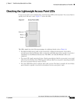
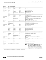
Checking the Lightweight Access Point LEDs Chapter 6 Troubleshooting Lightweight Access Points Table 6-1 Top Panel LED Signals Message type Ethernet LED Status LED Radio LED Meaning Boot loader status Green - - Amber Green Red DRAM memory test. Board initialization test - Blinking green Blinking green Flash memory test. Amber Green - Ethernet initialization test. Green Green Green Starting Cisco IOS. Association - status Green - At least one wireless client device is associated with the unit. - Blinking green - No client devices are associated; check the unit's SSID and WEP settings. Operating status - Green Green - Blinking green - Transmitting/receiving radio packets. Ethernet link is operational. Blinking green - - Transmitting/receiving Ethernet packets. Boot Loader Red - Red Errors - Red Red DRAM memory test failure. File system failure. Red Red - Ethernet failure during image recovery. Amber Green Amber Boot environment error. Red Green Red No Cisco IOS image file. Amber Amber Amber Boot failure. Operation Errors - Blinking amber Green - Blinking amber Maximum retries or buffer full occurred on the radio. - Transmit/receive Ethernet errors. - Blinking amber - General warning. Configuration - Reset Amber - Resetting the configuration options to factory defaults. Failure Red Red Red Firmware failure; try disconnecting and reconnecting unit power. Firmware Upgrade Controller status - Red - Alternating green, red , and amber1 Loading new firmware image. Connecting to the controller. Note If the access point remains in this mode for more than five minutes, the access point is unable to find the controller. Ensure a DHCP server is available or that the access point has been primed with the controller information. 1. This status indication has the highest priority and overrides other status indications. Cisco Aironet 1100 Series Access Point Hardware Installation Guide 6-4 OL-4309-07
-
 1
1 -
2
-
3
-
4
-
5
-
6
-
7
-
8
-
9
-
10
-
11
-
12
-
13
-
14
-
15
-
16
-
17
-
18
-
19
-
20
-
21
-
22
-
23
-
24
-
25
-
26
-
27
-
28
-
29
-
30
-
31
-
32
-
33
-
34
-
35
-
36
-
37
-
38
-
39
-
40
-
41
-
42
-
43
-
44
-
45
-
46
-
47
-
48
-
49
-
50
-
51
-
52
-
53
-
54
-
55
-
56
-
57
-
58
-
59
-
60
-
61
-
62
-
63
-
64
-
65
-
66
-
67
-
68
-
 69
69 -
 70
70 -
 71
71 -
 72
72 -
 73
73 -
 74
74 -
 75
75 -
 76
76 -
 77
77 -
 78
78 -
 79
79 -
80
-
81
-
82
-
83
-
84
-
85
-
86
-
87
-
88
-
89
-
90
-
91
-
92
-
93
-
94
-
95
-
96
-
97
-
98
-
99
-
100
-
101
-
102
-
103
-
104
-
105
-
106
-
107
-
108
-
109
-
110
-
111
-
112
-
113
-
114
-
115
-
116
 |
 |