Cisco AIR-LAP1131G-A-K9 Hardware Installation Guide - Page 97
and 12-100 ofthe Canadian ElectricalCode, Part1, C22.1.
 |
View all Cisco AIR-LAP1131G-A-K9 manuals
Add to My Manuals
Save this manual to your list of manuals |
Page 97 highlights
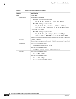
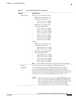
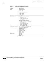
Appendix C Access Point Specifications Table C-1 Access Point Specifications (continued) Category Typical Range Antenna Compliance Specifications Indoor (across office cubicle walls): IEEE 802.11b-compliant radio: (maximum output power) 400 ft (121.9 m) at 1 Mbps 150 ft (45.7 m) at 11 Mbps IEEE 802.11g-compliant radio: (maximum output power) 410 ft ( 125.0 m) at 1 Mbps 270 ft ( 82.3 m) at 2 Mbps 220 ft ( 67.1 m) at 5.5 Mbps 160 ft ( 48.8 m) at 11 Mbps 300 ft ( 91.4 m) at 6 Mbps 210 ft (67.1 m) at 12 Mbps 180 ft (54.9 m) at 18 Mbps 90 ft ( 27.4 m) at 54 Mbps Outdoor: IEEE 802.11b-compliant radio: (maximum output power) 2000 ft (609.6 m) at 1 Mbps 800 ft (243.8 m) at 11 Mbps IEEE 802.11g-compliant radio: (maximum output power) 2000 ft (609.6 m) at 1 Mbps 1000 ft (304.8 m) at 11 Mbps 1300 ft (396.2 m) at 6 Mbps 600 ft (182.9 m) at 18 Mbps 250 ft (76.2 m) at 54 Mbps Note Using 2.2dBi antennas at the access point and the client adapter. A diversity system with two integrated 2.2 dBi dipole antennas. The1100 seriesaccesspointprovidesadequatefireresistanceand low sm oke-producing characteristicssuitableforoperation in abuilding's environm entalairspace,such asabovesuspended ceilings,in accordancew ith Section 300-22(C)oftheN ationalElectricalCode(N EC)and Sections2-128, 12-010(3)and 12-100 oftheCanadian ElectricalCode,Part1,C22.1. Caution Only the fiber-optic power injector (AIR-PWRINJ-FIB) has been tested to UL 2043 for operation in a building's environmental air space; no other power injectors or power modules have been tested to UL 2043 and they should not be placed in a building's environmental air space, such as above suspended ceilings. OL-4309-07 Cisco Aironet 1100 Series Access Point Hardware Installation Guide C-3
-
 1
1 -
2
-
3
-
4
-
5
-
6
-
7
-
8
-
9
-
10
-
11
-
12
-
13
-
14
-
15
-
16
-
17
-
18
-
19
-
20
-
21
-
22
-
23
-
24
-
25
-
26
-
27
-
28
-
29
-
30
-
31
-
32
-
33
-
34
-
35
-
36
-
37
-
38
-
39
-
40
-
41
-
42
-
43
-
44
-
45
-
46
-
47
-
48
-
49
-
50
-
51
-
52
-
53
-
54
-
55
-
56
-
57
-
58
-
59
-
60
-
61
-
62
-
63
-
64
-
65
-
66
-
67
-
68
-
69
-
70
-
71
-
72
-
73
-
74
-
75
-
76
-
77
-
78
-
79
-
80
-
81
-
82
-
83
-
84
-
85
-
86
-
87
-
88
-
89
-
90
-
91
-
 92
92 -
 93
93 -
 94
94 -
 95
95 -
 96
96 -
 97
97 -
 98
98 -
 99
99 -
 100
100 -
 101
101 -
 102
102 -
103
-
104
-
105
-
106
-
107
-
108
-
109
-
110
-
111
-
112
-
113
-
114
-
115
-
116
 |
 |