Cisco AIR-LAP1141N-A-K9 Getting Started Guide - Page 12
Mounting the Access Point, 7 Deploying the Access Point on the Wireless Network - antenna
 |
UPC - 882658245978
View all Cisco AIR-LAP1141N-A-K9 manuals
Add to My Manuals
Save this manual to your list of manuals |
Page 12 highlights
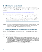
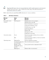
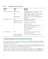
6 Mounting the Access Point Cisco Aironet 3500, 1260, 1140, 1130, and 1040 series access points can be mounted in several configurations, including on a suspended ceiling, on a hard ceiling or wall, on an elecrtical or network box, and above a suspended ceiling. Click this URL to browse to complete access point mounting instructions: http://www.cisco.com/en/US/docs/wireless/access_point/mounting/guide/apmount.html Note The integrated antenna design of the 1140 series access point is designed for horizontal surfaces, (table top and ceiling installations). When mounted to such surfaces, the integrated antennas produce the best antenna radiation pattern. For advanced features such as voice, location, and rogue access point detection, ceiling mounting is strongly recommended. However, for smaller areas such as conference rooms, kiosks, transportation, and hot-spot usage where the customer is concerned primarily with data coverage and not advanced features, you can mount the unit on a wall using wall anchors. Caution Do not use plastic wall anchors or the keyhole slots on the mounting bracket for ceiling installations. When mounting the access point on a hard ceiling, use four fasteners capable of maintaining a minimum pullout force of 20 lbs (9 kg). 7 Deploying the Access Point on the Wireless Network After you have mounted the access point, follow these steps to deploy it on the wireless network. Step 1 Step 2 Connect and power up the access point. Observe the access point LED. a. When you power up the access point, it begins a power-up sequence that you can verify by observing the access point LED. If the power-up sequence is successful, the discovery and join process begins. During this process, the LED blinks sequentially through its available colors (red, amber, and green). When the access point has joined a controller, the LED is green if no clients are associated or blue if one or more clients are associated. b. If the LED is not on, the access point is most likely not receiving power. 12
-
 1
1 -
2
-
3
-
4
-
5
-
6
-
 7
7 -
 8
8 -
 9
9 -
 10
10 -
 11
11 -
 12
12 -
 13
13 -
 14
14 -
 15
15 -
 16
16 -
 17
17 -
18
-
19
-
20
-
21
-
22
-
23
-
24
-
25
-
26
-
27
-
28
-
29
-
30
-
31
-
32
-
33
-
34
 |
 |