Cisco ASR1006 Hardware Installation Guide - Page 104
Smart Serial Cable Connectors, Table 3-39, Smart Serial Connector Pinouts, O_TXCE/RXC
 |
UPC - 882658196423
View all Cisco ASR1006 manuals
Add to My Manuals
Save this manual to your list of manuals |
Page 104 highlights
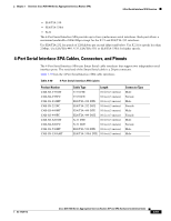
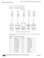
4-Port Serial Interface SPA Overview Chapter 3 Overview: Cisco ASR 1000 Series Aggregation Services Routers SPAs Figure 3-40 shows the Smart Serial cable connectors. Figure 3-40 Smart Serial Cable Connectors Router connections 205059 EIA/TIA-232 EIA/TIA-449 V.35 X.21 Network connections at the modem or CSU/DSU EIA-530 Table 3-39 lists the connector pinouts for the Smart Serial connectors that interface at the 4-Port Serial Interface SPA ports. Table 3-39 Smart Serial Connector Pinouts Pin Signal Pin Signal 1 O_TXD/RXD+ 14 O_TXD/RXD- 2 O_TXCE/RXC+ 15 O_TXCE/RXC- 3 B_TXC/TXC+ 16 B_TXC/TXC- 4 I_RXC/TXCE+ 17 I_RXC/TXCE- 5 I_RXD/TXD+ 18 I_RXD/TXD- 6 B_DCD/DCD+ 19 B_DCD/DCD- 7 O_DTR/DSR+ 20 O_DTR/DSR- 8 O_RTS/CTS+ 21 MODE2 9 O_RTS/CTS- 22 MODE1 10 I_CTS/RTS- 23 MODE0 11 I_CTS/RTS+ 24 MODEDCE 3-62 Cisco ASR 1000 Series Aggregation Services Routers SIP and SPA Hardware Installation Guide OL-14126-12
-
 1
1 -
2
-
3
-
4
-
5
-
6
-
7
-
8
-
9
-
10
-
11
-
12
-
13
-
14
-
15
-
16
-
17
-
18
-
19
-
20
-
21
-
22
-
23
-
24
-
25
-
26
-
27
-
28
-
29
-
30
-
31
-
32
-
33
-
34
-
35
-
36
-
37
-
38
-
39
-
40
-
41
-
42
-
43
-
44
-
45
-
46
-
47
-
48
-
49
-
50
-
51
-
52
-
53
-
54
-
55
-
56
-
57
-
58
-
59
-
60
-
61
-
62
-
63
-
64
-
65
-
66
-
67
-
68
-
69
-
70
-
71
-
72
-
73
-
74
-
75
-
76
-
77
-
78
-
79
-
80
-
81
-
82
-
83
-
84
-
85
-
86
-
87
-
88
-
89
-
90
-
91
-
92
-
93
-
94
-
95
-
96
-
97
-
98
-
 99
99 -
 100
100 -
 101
101 -
 102
102 -
 103
103 -
 104
104 -
 105
105 -
 106
106 -
 107
107 -
 108
108 -
 109
109 -
110
-
111
-
112
-
113
-
114
-
115
-
116
-
117
-
118
-
119
-
120
-
121
-
122
-
123
-
124
-
125
-
126
-
127
-
128
-
129
-
130
-
131
-
132
-
133
-
134
-
135
-
136
-
137
-
138
-
139
-
140
-
141
-
142
-
143
-
144
-
145
-
146
-
147
-
148
-
149
-
150
-
151
-
152
-
153
-
154
-
155
-
156
-
157
-
158
-
159
-
160
-
161
-
162
-
163
-
164
-
165
-
166
-
167
-
168
-
169
-
170
-
171
-
172
-
173
-
174
-
175
-
176
-
177
-
178
-
179
-
180
-
181
-
182
-
183
-
184
-
185
-
186
-
187
-
188
 |
 |
