Cisco ASR1006 Hardware Installation Guide - Page 106
-Port Channelized T1/E1 Serial SPA Interface Specifications
 |
UPC - 882658196423
View all Cisco ASR1006 manuals
Add to My Manuals
Save this manual to your list of manuals |
Page 106 highlights
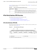
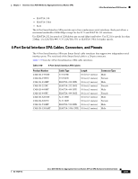
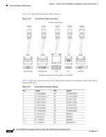
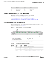
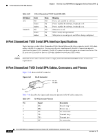
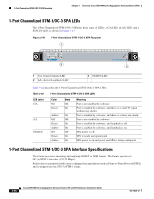
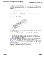
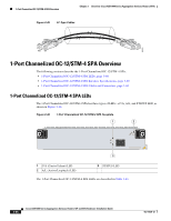
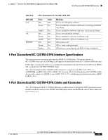
8-Port Channelized T1/E1 SPA Overview Chapter 3 Overview: Cisco ASR 1000 Series Aggregation Services Routers SPAs Table 3-40 LED Label A/L STATUS 8-Port Channelized T1/E1 Serial SPA LEDs Color Off Green Amber Off Green Amber State Off On On Off On On Meaning Port is not enabled by software. Port is enabled by software, loopback is off. Port is enabled by software, loopback is on. SPA power is off. SPA is ready and operational. SPA power is on and good, and SPA is being configured. 8-Port Channelized T1/E1 Serial SPA Interface Specifications The E1 interface on the 8-Port Channelized T1/E1 Serial SPA uses RJ-48c receptacles for E1 (120-ohm) cables with RJ-45 connectors. You can use all ports simultaneously. Each E1 connection supports interfaces that meet G.703 standards. The RJ-45 connection does not require an external transceiver. The E1 ports are E1 interfaces that use 120-ohm shielded twisted pair (STP) cables. Caution Shielded T1/E1 cables must be used to comply with FCC/EN55022/CISPR22 Class A emissions requirements. 8-Port Channelized T1/E1 Serial SPA Cables, Connectors, and Pinouts Figure 3-42 shows an RJ-45 connector. Figure 3-42 RJ-45 Connector RJ-45 RJ-48c 32770 Pin 1 Pin 8 Table 3-41 describes the signals and connector pinouts for RJ-45 cable connectors. Table 3-41 RJ-45 Connector Pinouts Pin Signal 1 RX- 2 RX+ 3 NC 4 TX- 5 TX+ 6 NC Description Receive ring - Receive tip + No connection Transmit ring - Transmit tip + No connection 3-64 Cisco ASR 1000 Series Aggregation Services Routers SIP and SPA Hardware Installation Guide OL-14126-12
-
 1
1 -
2
-
3
-
4
-
5
-
6
-
7
-
8
-
9
-
10
-
11
-
12
-
13
-
14
-
15
-
16
-
17
-
18
-
19
-
20
-
21
-
22
-
23
-
24
-
25
-
26
-
27
-
28
-
29
-
30
-
31
-
32
-
33
-
34
-
35
-
36
-
37
-
38
-
39
-
40
-
41
-
42
-
43
-
44
-
45
-
46
-
47
-
48
-
49
-
50
-
51
-
52
-
53
-
54
-
55
-
56
-
57
-
58
-
59
-
60
-
61
-
62
-
63
-
64
-
65
-
66
-
67
-
68
-
69
-
70
-
71
-
72
-
73
-
74
-
75
-
76
-
77
-
78
-
79
-
80
-
81
-
82
-
83
-
84
-
85
-
86
-
87
-
88
-
89
-
90
-
91
-
92
-
93
-
94
-
95
-
96
-
97
-
98
-
99
-
100
-
 101
101 -
 102
102 -
 103
103 -
 104
104 -
 105
105 -
 106
106 -
 107
107 -
 108
108 -
 109
109 -
 110
110 -
 111
111 -
112
-
113
-
114
-
115
-
116
-
117
-
118
-
119
-
120
-
121
-
122
-
123
-
124
-
125
-
126
-
127
-
128
-
129
-
130
-
131
-
132
-
133
-
134
-
135
-
136
-
137
-
138
-
139
-
140
-
141
-
142
-
143
-
144
-
145
-
146
-
147
-
148
-
149
-
150
-
151
-
152
-
153
-
154
-
155
-
156
-
157
-
158
-
159
-
160
-
161
-
162
-
163
-
164
-
165
-
166
-
167
-
168
-
169
-
170
-
171
-
172
-
173
-
174
-
175
-
176
-
177
-
178
-
179
-
180
-
181
-
182
-
183
-
184
-
185
-
186
-
187
-
188
 |
 |