Cisco ASR1006 Hardware Installation Guide - Page 122
-Port Channelized T1/E1/J1 CEoP SPA Interface Specifications, 24-Port Channelized T1/E1/J1 CEoP
 |
UPC - 882658196423
View all Cisco ASR1006 manuals
Add to My Manuals
Save this manual to your list of manuals |
Page 122 highlights
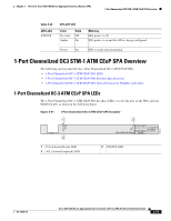
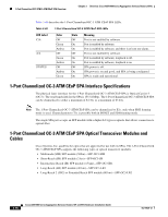
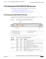
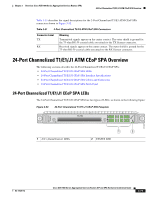
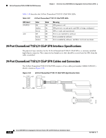
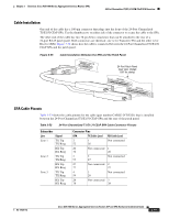
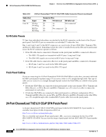
24-Port Channelized T1/E1/J1 ATM CEoP SPA Overview Chapter 3 Overview: Cisco ASR 1000 Series Aggregation Services Routers SPAs Table 3-49 describes the 24-Port Channelized T1/E1/J1 CEoP SPA LEDs. Table 3-52 24-Port Channelized T1/E1/J1 CEoP SPA LEDs LED Label STATUS A/C Color Off Amber Green Off Green Amber State Off On On Off On On Meaning SPA power is off. SPA power is on and good, and SPA is being configured. SPA is ready and operational. Port is not enabled by software. Port is enabled by software. Port is enabled by software, and there is at least one alarm. 24-Port Channelized T1/E1/J1 CEoP SPA Interface Specifications The physical layer interface for the 24-Port Channelized T1/E1/J1 CEoP SPA is a customer-installed high-density connector. This connector has thumbscrews that should be screwed into the SPA when the cable is installed. 24-Port Channelized T1/E1/J1 CEoP SPA Cables and Connectors The 24-Port Channelized T1/E1/J1 CEoP SPA requires a Cisco cable (part number CABLE-24T1E1J1), which is shown in Figure 3-54. Figure 3-54 24-Port Channelized T1/E1/J1 CEoP SPA High-Density Cable 1 51 50 100 50 26 25 1 250106 3-80 Cisco ASR 1000 Series Aggregation Services Routers SIP and SPA Hardware Installation Guide OL-14126-12
-
 1
1 -
2
-
3
-
4
-
5
-
6
-
7
-
8
-
9
-
10
-
11
-
12
-
13
-
14
-
15
-
16
-
17
-
18
-
19
-
20
-
21
-
22
-
23
-
24
-
25
-
26
-
27
-
28
-
29
-
30
-
31
-
32
-
33
-
34
-
35
-
36
-
37
-
38
-
39
-
40
-
41
-
42
-
43
-
44
-
45
-
46
-
47
-
48
-
49
-
50
-
51
-
52
-
53
-
54
-
55
-
56
-
57
-
58
-
59
-
60
-
61
-
62
-
63
-
64
-
65
-
66
-
67
-
68
-
69
-
70
-
71
-
72
-
73
-
74
-
75
-
76
-
77
-
78
-
79
-
80
-
81
-
82
-
83
-
84
-
85
-
86
-
87
-
88
-
89
-
90
-
91
-
92
-
93
-
94
-
95
-
96
-
97
-
98
-
99
-
100
-
101
-
102
-
103
-
104
-
105
-
106
-
107
-
108
-
109
-
110
-
111
-
112
-
113
-
114
-
115
-
116
-
 117
117 -
 118
118 -
 119
119 -
 120
120 -
 121
121 -
 122
122 -
 123
123 -
 124
124 -
 125
125 -
 126
126 -
 127
127 -
128
-
129
-
130
-
131
-
132
-
133
-
134
-
135
-
136
-
137
-
138
-
139
-
140
-
141
-
142
-
143
-
144
-
145
-
146
-
147
-
148
-
149
-
150
-
151
-
152
-
153
-
154
-
155
-
156
-
157
-
158
-
159
-
160
-
161
-
162
-
163
-
164
-
165
-
166
-
167
-
168
-
169
-
170
-
171
-
172
-
173
-
174
-
175
-
176
-
177
-
178
-
179
-
180
-
181
-
182
-
183
-
184
-
185
-
186
-
187
-
188
 |
 |