Cisco ASR1006 Hardware Installation Guide - Page 52
-Port Clear Channel OC-12 ATM SPA LEDs - asr power specifications
 |
UPC - 882658196423
View all Cisco ASR1006 manuals
Add to My Manuals
Save this manual to your list of manuals |
Page 52 highlights
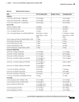
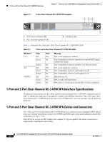
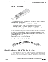
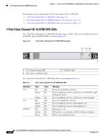
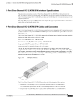
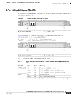
STATUS 270703 1-Port Clear Channel OC-12 ATM SPA Overview Chapter 3 Overview: Cisco ASR 1000 Series Aggregation Services Routers SPAs The following sections describe the 1-Port Clear Channel OC-12 ATM SPA: • 1-Port Clear Channel OC-12 ATM SPA LEDs, page 3-10 • 1-Port Clear Channel OC-12 ATM SPA Interface Specifications, page 3-11 • 1-Port Clear Channel OC-12 ATM SPA Cables and Connectors, page 3-11 1-Port Clear Channel OC-12 ATM SPA LEDs The 1-Port Clear Channel OC-12 ATM SPA has three types of LEDs. There are two LEDs for the port on the SPA, and one STATUS LED, as shown in Figure 3-4. Figure 3-4 1-Port Clear Channel OC-12 ATM SPA Faceplate 1 23 C/A A/L Port 0 0 SPA-1XOC12-ATM-V2 1 C/A (Carrier/Alarm) LED 2 A/L (Active Loopback) LED 3 STATUS LED The 1-Port Clear Channel OC-12 ATM SPA LEDs are described in Table 3-4. Table 3-4 1-Port Clear Channel OC-12 ATM SPA LEDs LED Label C/A A/L STATUS Color Off Green Amber Off Green Amber Off Amber Green State Off On On Off On On Off On On Meaning Port is not enabled by software. Port is enabled by software, and there is a valid SONET signal without any alarms. Port is enabled by software, and there is at least one alarm. Port is not enabled by software. Port is enabled by software, and loopback is off. Port is enabled by software, and loopback is on. SPA power is off. SPA power is on and good, and SPA is being configured. SPA is ready and operational. 3-10 Cisco ASR 1000 Series Aggregation Services Routers SIP and SPA Hardware Installation Guide OL-14126-12
-
 1
1 -
2
-
3
-
4
-
5
-
6
-
7
-
8
-
9
-
10
-
11
-
12
-
13
-
14
-
15
-
16
-
17
-
18
-
19
-
20
-
21
-
22
-
23
-
24
-
25
-
26
-
27
-
28
-
29
-
30
-
31
-
32
-
33
-
34
-
35
-
36
-
37
-
38
-
39
-
40
-
41
-
42
-
43
-
44
-
45
-
46
-
 47
47 -
 48
48 -
 49
49 -
 50
50 -
 51
51 -
 52
52 -
 53
53 -
 54
54 -
 55
55 -
 56
56 -
 57
57 -
58
-
59
-
60
-
61
-
62
-
63
-
64
-
65
-
66
-
67
-
68
-
69
-
70
-
71
-
72
-
73
-
74
-
75
-
76
-
77
-
78
-
79
-
80
-
81
-
82
-
83
-
84
-
85
-
86
-
87
-
88
-
89
-
90
-
91
-
92
-
93
-
94
-
95
-
96
-
97
-
98
-
99
-
100
-
101
-
102
-
103
-
104
-
105
-
106
-
107
-
108
-
109
-
110
-
111
-
112
-
113
-
114
-
115
-
116
-
117
-
118
-
119
-
120
-
121
-
122
-
123
-
124
-
125
-
126
-
127
-
128
-
129
-
130
-
131
-
132
-
133
-
134
-
135
-
136
-
137
-
138
-
139
-
140
-
141
-
142
-
143
-
144
-
145
-
146
-
147
-
148
-
149
-
150
-
151
-
152
-
153
-
154
-
155
-
156
-
157
-
158
-
159
-
160
-
161
-
162
-
163
-
164
-
165
-
166
-
167
-
168
-
169
-
170
-
171
-
172
-
173
-
174
-
175
-
176
-
177
-
178
-
179
-
180
-
181
-
182
-
183
-
184
-
185
-
186
-
187
-
188
 |
 |