Cisco ASR1006 Hardware Installation Guide - Page 62
-Port Gigabit Ethernet SPA Overview, 5-Port Gigabit Ethernet SPA LEDs
 |
UPC - 882658196423
View all Cisco ASR1006 manuals
Add to My Manuals
Save this manual to your list of manuals |
Page 62 highlights
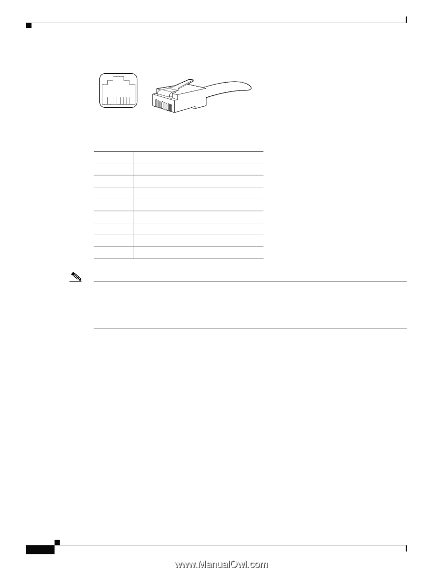
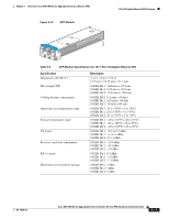
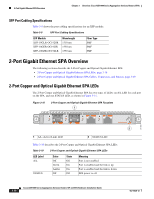
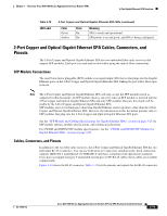
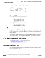
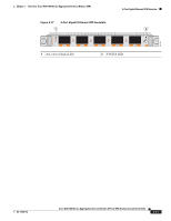
5-Port Gigabit Ethernet SPA Overview Chapter 3 Overview: Cisco ASR 1000 Series Aggregation Services Routers SPAs Figure 3-16 RJ-45 Connector Pinouts, Plug, and Receptacle 205060 8 7 6 5 4 3 2 1 RJ-45 connector Table 3-11 RJ-45 Connector Pinouts Pin Description 1 DA_P (bidirectional pair A, plus) 2 DA_N (bidirectional pair A, minus) 3 DB_P (bidirectional pair B, plus) 4 DC_P (bidirectional pair C, plus) 5 DC_N (bidirectional pair C, minus) 6 DB_N (bidirectional pair B, minus) 7 DD_P (bidirectional pair D, plus) 8 DD_N (bidirectional pair D, minus) Note Referring to the RJ-45 pinout in Table 3-11, proper common-mode line terminations should be used for the unused Category 5 UTP cable pairs 4/5 and 7/8. Common-mode termination reduces the contributions to electromagnetic interference (EMI) and susceptibility to common-mode sources. Wire pairs 4/5 and 7/8 are actively terminated in the RJ-45 port circuitry in the 2-Port Copper and Optical Gigabit Ethernet SPA. The 2-Port Copper and Optical Gigabit Ethernet SPA supports automatic MDI/MDIX crossover at all speeds of operation allowing the SPA to work with straight-through and crossover Ethernet cables. 5-Port Gigabit Ethernet SPA Overview The following sections describe the 5-Port Gigabit Ethernet SPA: • 5-Port Gigabit Ethernet SPA LEDs, page 3-20 • 5-Port Gigabit Ethernet SPA Connectors, page 3-22 5-Port Gigabit Ethernet SPA LEDs The 5-Port Gigabit Ethernet SPA has two types of LEDs: an A/L LED for each port on the SPA, and one STATUS LED, as shown in Figure 3-17. 3-20 Cisco ASR 1000 Series Aggregation Services Routers SIP and SPA Hardware Installation Guide OL-14126-12
-
 1
1 -
2
-
3
-
4
-
5
-
6
-
7
-
8
-
9
-
10
-
11
-
12
-
13
-
14
-
15
-
16
-
17
-
18
-
19
-
20
-
21
-
22
-
23
-
24
-
25
-
26
-
27
-
28
-
29
-
30
-
31
-
32
-
33
-
34
-
35
-
36
-
37
-
38
-
39
-
40
-
41
-
42
-
43
-
44
-
45
-
46
-
47
-
48
-
49
-
50
-
51
-
52
-
53
-
54
-
55
-
56
-
 57
57 -
 58
58 -
 59
59 -
 60
60 -
 61
61 -
 62
62 -
 63
63 -
 64
64 -
 65
65 -
 66
66 -
 67
67 -
68
-
69
-
70
-
71
-
72
-
73
-
74
-
75
-
76
-
77
-
78
-
79
-
80
-
81
-
82
-
83
-
84
-
85
-
86
-
87
-
88
-
89
-
90
-
91
-
92
-
93
-
94
-
95
-
96
-
97
-
98
-
99
-
100
-
101
-
102
-
103
-
104
-
105
-
106
-
107
-
108
-
109
-
110
-
111
-
112
-
113
-
114
-
115
-
116
-
117
-
118
-
119
-
120
-
121
-
122
-
123
-
124
-
125
-
126
-
127
-
128
-
129
-
130
-
131
-
132
-
133
-
134
-
135
-
136
-
137
-
138
-
139
-
140
-
141
-
142
-
143
-
144
-
145
-
146
-
147
-
148
-
149
-
150
-
151
-
152
-
153
-
154
-
155
-
156
-
157
-
158
-
159
-
160
-
161
-
162
-
163
-
164
-
165
-
166
-
167
-
168
-
169
-
170
-
171
-
172
-
173
-
174
-
175
-
176
-
177
-
178
-
179
-
180
-
181
-
182
-
183
-
184
-
185
-
186
-
187
-
188
 |
 |