Cisco CISCO804-IDSL Hardware Installation Guide
Cisco CISCO804-IDSL - 804 Router Manual
 |
UPC - 746320318097
View all Cisco CISCO804-IDSL manuals
Add to My Manuals
Save this manual to your list of manuals |
Cisco CISCO804-IDSL manual content summary:
- Cisco CISCO804-IDSL | Hardware Installation Guide - Page 1
Cisco 800 Series Routers Hardware Installation Guide Corporate Headquarters Cisco Systems, Inc. 170 West Tasman Drive San Jose, CA 95134-1706 USA http://www.cisco.com Tel: 408 526-4000 800 553-NETS (6387) Fax: 408 526-4100 Customer Order Number: DOC-785373= Text Part Number: 78-5373-04 - Cisco CISCO804-IDSL | Hardware Installation Guide - Page 2
energy. If it is not installed in accordance with Cisco's installation instructions, it may cause interference with radio and television reception. This equipment has been tested and found to comply with the limits for a Class B digital device in accordance with the specifications in part 15 of the - Cisco CISCO804-IDSL | Hardware Installation Guide - Page 3
Study are service marks of Cisco Systems, Inc.; and Access Registrar, Aironet, ASIST, BPX, Catalyst, CCDA, CCDP, CCIE, CCIP, CCNA, CCNP, Cisco, the Cisco Certified Internetwork Expert logo, Cisco IOS, Cisco Press, Cisco Systems, Cisco Systems Capital, the Cisco Systems logo, Cisco Unity, Empowering - Cisco CISCO804-IDSL | Hardware Installation Guide - Page 4
- Cisco CISCO804-IDSL | Hardware Installation Guide - Page 5
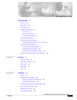
Cisco Product Security Overview x Reporting Security Problems in Cisco Products x Obtaining Technical Assistance xi Cisco Technical Support Website xi Submitting a Service Request xii Definitions of Service 2-4 Preinstallation Activities 2-4 Cisco 800 Series Routers Hardware Installation Guide v - Cisco CISCO804-IDSL | Hardware Installation Guide - Page 6
, Fax, or Modem 2-15 Connecting a Terminal or PC 2-17 Connecting the Power Supply 2-18 Mounting Your Router 2-18 Mounting on a Table 2-18 Mounting on a Wall 2-19 Verifying Installation 2-20 Where to Go from Here 2-22 Troubleshooting 3-1 Problems During First Startup 3-2 Problems After First Startup - Cisco CISCO804-IDSL | Hardware Installation Guide - Page 7
preparing for installation as well as installing, mounting, and verifying the connections to your router. • Troubleshooting-Describes how to identify and solve problems with your router. • ISDN and IDSL Concepts-Describes how ISDN is implemented on the router. • Specifications and Cables-Provides - Cisco CISCO804-IDSL | Hardware Installation Guide - Page 8
Conventions About This Guide Caution This symbol means reader be careful. In this situation, you might do something relacionados com circuitos eléctricos, e com quaisquer práticas comuns que possam prevenir possíveis acidentes. Cisco 800 Series Routers Hardware Installation Guide viii 78-5373-04 - Cisco CISCO804-IDSL | Hardware Installation Guide - Page 9
.com/en/US/partner/ordering/ Cisco Marketplace: http://www.cisco.com/go/marketplace/ Ordering Documentation You can find instructions for ordering documentation at this URL: http://www.cisco.com/univercd/cc/td/doc/es_inpck/pdi.htm 78-5373-04 Cisco 800 Series Routers Hardware Installation Guide ix - Cisco CISCO804-IDSL | Hardware Installation Guide - Page 10
URL: http://www.cisco.com/en/US/products/products_psirt_rss_feed.html Reporting Security Problems in Cisco Products Cisco is committed to a Cisco product, contact PSIRT: • Emergencies - [email protected] • Nonemergencies - [email protected] Cisco 800 Series Routers Hardware Installation Guide x - Cisco CISCO804-IDSL | Hardware Installation Guide - Page 11
Cisco service contract, contact your reseller. Cisco Technical Support Website The Cisco Technical Support Website provides online documents and tools for troubleshooting and resolving technical issues with Cisco a service call. 78-5373-04 Cisco 800 Series Routers Hardware Installation Guide xi - Cisco CISCO804-IDSL | Hardware Installation Guide - Page 12
most business operations remain functional. You and Cisco will commit resources during normal business hours to restore service to satisfactory levels. Severity 4 (S4)-You require information or assistance with Cisco product capabilities, installation, or configuration. There is little or no effect - Cisco CISCO804-IDSL | Hardware Installation Guide - Page 13
delivers coverage of the latest industry trends, technology breakthroughs, and Cisco products and solutions, as well as network deployment and troubleshooting tips, configuration examples, customer case studies, certification and training information, and links to scores of in-depth online resources - Cisco CISCO804-IDSL | Hardware Installation Guide - Page 14
Obtaining Additional Publications and Information About This Guide Cisco 800 Series Routers Hardware Installation Guide xiv 78-5373-04 - Cisco CISCO804-IDSL | Hardware Installation Guide - Page 15
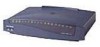
CH A P T E R 1 The Cisco 800 series routers connect small professional offices or telecommuters over Integrated Services Digital Network (ISDN) Basic Rate Interface (BRI Ports Summary • Front Panels • Back Panels • LEDs 78-5373-04 Cisco 800 Series Routers Hardware Installation Guide 1-1 - Cisco CISCO804-IDSL | Hardware Installation Guide - Page 16
of error. Supports Cisco IOS software. Provides a Windows 95-, Windows 98-, and Windows NT-based software tool for basic configurations. Provides connection to terminal or PC for software configuration using command-line interface and for troubleshooting. Note The console port is a service port - Cisco CISCO804-IDSL | Hardware Installation Guide - Page 17
Cisco 800 series routers. Figure 1-1 Cisco 801, Cisco 802, and Cisco 802 IDSL Front Panel NT1 LED on Cisco 802 and 802 IDSL routers only Figure 1-2 Cisco 803 and Cisco 804 Front Panel 11665 NT1 LED on Cisco 804 router only 11664 78-5373-04 Cisco 800 Series Routers Hardware Installation Guide - Cisco CISCO804-IDSL | Hardware Installation Guide - Page 18
to physically secure router. HUB/NO HUB button (for Ethernet port) Console port Determines cable Connect PC or type for Ethernet terminal. device connection. Locking power connector Connect power supply. Cisco 800 Series Routers Hardware Installation Guide 1-4 78-5373-04 - Cisco CISCO804-IDSL | Hardware Installation Guide - Page 19
T 0 1 2 3 Cisco 803 CONSOLE ISDN S/T HUB/NO HUB button (for Ethernet port 0) Determines cable type for Ethernet device connection. Console port Connect PC or terminal. PHONE 1 2 Locking power connector Connect power supply. 78-5373-04 Cisco 800 Series Routers Hardware Installation Guide 1-5 - Cisco CISCO804-IDSL | Hardware Installation Guide - Page 20
to physically secure router. TO HUB/TO PC (for Ethernet port) Determines cable type for Ethernet device connection. Console port Connect PC or terminal. Locking power connector Connect power supply. 30771 Cisco 800 Series Routers Hardware Installation Guide 1-6 78-5373-04 - Cisco CISCO804-IDSL | Hardware Installation Guide - Page 21
See the "Troubleshooting" chapter. Cisco 804 IDSL routers only. On when the Ethernet device is connected. Off when the Ethernet device is not connected. Blinks when the connection has a problem. See the "Troubleshooting" chapter. 78-5373-04 Cisco 800 Series Routers Hardware Installation Guide 1-7 - Cisco CISCO804-IDSL | Hardware Installation Guide - Page 22
service is in use. On back panel of Cisco 801, 802, and 802 IDSL routers only. On when Ethernet device is connected. Blinks when the connection has a problem. Refer to the "Troubleshooting" chapter. Note On Cisco 802 IDSL and Cisco Cisco 800 Series Routers Hardware Installation Guide 1-8 78-5373-04 - Cisco CISCO804-IDSL | Hardware Installation Guide - Page 23
• Preventing Electrostatic Discharge Damage • Preventing Router Damage • Unpacking Your Router • Preinstallation Activities • Installing Your Router • Mounting Your Router • Verifying Installation • Where to Go from Here 78-5373-04 Cisco 800 Series Routers Hardware Installation Guide 2-1 - Cisco CISCO804-IDSL | Hardware Installation Guide - Page 24
trained and qualified personnel should be allowed to install or replace this equipment. Warning Read the installation instructions before you connect the system to its power Cisco 801 routers and Cisco 803 routers sold in the European Union (EU). Cisco 800 Series Routers Hardware Installation Guide - Cisco CISCO804-IDSL | Hardware Installation Guide - Page 25
synthetic fibers and dry atmosphere. Always use the following ESD-prevention procedures when removing and replacing components: 1. Connect the chassis to earth ground with a wire that you provide. between 1 and 10 megohms (Mohms). 78-5373-04 Cisco 800 Series Routers Hardware Installation Guide 2-3 - Cisco CISCO804-IDSL | Hardware Installation Guide - Page 26
Step 1 Step 2 Order an ISDN BRI line from your telephone service provider. For more information, refer to the Cisco 800 Series Routers Software Configuration Guide. If you have a Cisco 801 or Cisco 803 router, do the following: Cisco 800 Series Routers Hardware Installation Guide 2-4 78-5373-04 - Cisco CISCO804-IDSL | Hardware Installation Guide - Page 27
telephone service provider Specifications modem. 5. Connect a terminal or PC to the router (for software configuration using the command-line interface [CLI] or for troubleshooting). 6. Connect the router to the power source. 7. Mount your router. 8. Verify the router installation. 78-5373-04 Cisco - Cisco CISCO804-IDSL | Hardware Installation Guide - Page 28
Router Router Port Hub with equivalent to router HUB/NO HUB button Cisco 801 and 802 routers: Ethernet port Cisco 803 and 804 routers: Ethernet port Ø Hub with equivalent to (IN) MDI-X (OUT) MDI-X (OUT) MDI-X (OUT) MDI-X (OUT) Cisco 800 Series Routers Hardware Installation Guide 2-6 78-5373-04 - Cisco CISCO804-IDSL | Hardware Installation Guide - Page 29
hub. Refer to your hub documentation for details. 3. On Cisco 803 and Cisco 804 routers, the HUB/NO HUB button affects only Ethernet port Ø. 4. On Cisco 804 IDSL routers, the TO HUB/TO PC button affects only Ethernet port 1. 78-5373-04 Cisco 800 Series Routers Hardware Installation Guide 2-7 - Cisco CISCO804-IDSL | Hardware Installation Guide - Page 30
, or 802 IDSL back panel. • LKØ, LK1, LK2, or LK3 LED on the Cisco 803 or Cisco 804 front panel. • ETHERNET 1, 2, 3, or 4 LED on the Cisco 804 IDSL front panel. If the LED is not on, see Table 3-2 in Chapter 3, "Troubleshooting." Cisco 800 Series Routers Hardware Installation Guide 2-8 78-5373-04 - Cisco CISCO804-IDSL | Hardware Installation Guide - Page 31
, or 802 IDSL back panel. • LKØ, LK1, LK2, or LK3 LED on the Cisco 803 or Cisco 804 front panel. • ETHERNET 1, 2, 3, or 4 LED on the Cisco 804 IDSL front panel. If the LED is not on, see Table 3-2 in Chapter 3, "Troubleshooting." 78-5373-04 Cisco 800 Series Routers Hardware Installation Guide 2-9 - Cisco CISCO804-IDSL | Hardware Installation Guide - Page 32
do not support the Australian IUT requirement, which specifies that the routers must communicate for 1/2 hour after a power failure. If a power failure occurs, a Cisco 800 series router stops communicating with other devices. 2-10 Cisco 800 Series Routers Hardware Installation Guide 78-5373 - Cisco CISCO804-IDSL | Hardware Installation Guide - Page 33
cable to orange ISDN S/T port. NT1 5. Connect NT1 power cord to electrical outlet. ISDN wall jack 2. Connect other end of cable to NT1. 3. Connect ISDN U cable to NT1. 4. Connect other end of cable to ISDN wall jack. 11676 78-5373-04 Cisco 800 Series Routers Hardware Installation Guide 2-11 - Cisco CISCO804-IDSL | Hardware Installation Guide - Page 34
do not support the Australian IUT requirement, which specifies that the routers must communicate for 1/2 hour after a power failure. If a power failure occurs, a Cisco 800 series router stops communicating with other devices. 2-12 Cisco 800 Series Routers Hardware Installation Guide 78-5373 - Cisco CISCO804-IDSL | Hardware Installation Guide - Page 35
not support the Australian IUT requirement, which specifies that the routers must communicate for 1/2 hour after a power failure. If a power failure occurs, a Cisco 802 IDSL or 804 IDSL router stops communicating with other devices. 78-5373-04 Cisco 800 Series Routers Hardware Installation Guide - Cisco CISCO804-IDSL | Hardware Installation Guide - Page 36
a Digital Telephone You can connect a digital telephone, also known as an ISDN telephone, to the ISDN S/T port on Cisco 801 and Cisco 803 routers. This device connects to basic telephone services through the ISDN line. 2-14 Cisco 800 Series Routers Hardware Installation Guide 78-5373-04 - Cisco CISCO804-IDSL | Hardware Installation Guide - Page 37
are outside of North America, you must buy and attach adapters that allow your telephones, faxes, or modems to be connected to these RJ-11 connectors. In some countries, these adapters need additional electronics to convert the 78-5373-04 Cisco 800 Series Routers Hardware Installation Guide 2-15 - Cisco CISCO804-IDSL | Hardware Installation Guide - Page 38
Router Chapter 2 Installation telephones, faxes, or modems to work properly with the router phone ports. For example, in the United Kingdom, you must buy an adapter that Adapter (part number 2797057) http://www.tandy.co.uk/ 2-16 Cisco 800 Series Routers Hardware Installation Guide 78-5373-04 - Cisco CISCO804-IDSL | Hardware Installation Guide - Page 39
Chapter 2 Installation Installing Your Router Connecting a Terminal or PC You can connect either a terminal or a PC from which you can configure the software via the CLI or troubleshoot. To connect a terminal or PC, follow the steps in Figure 2-9. Figure 2-9 Connecting Terminal or PC Cisco 804 - Cisco CISCO804-IDSL | Hardware Installation Guide - Page 40
Router Chapter 2 Installation Connecting the Power Supply To connect the power supply, follow the steps in Figure 2-10. Warning The device is designed to work with TN power systems. Warning This product relies on the building's installation for short-circuit (overcurrent) protection. Ensure that - Cisco CISCO804-IDSL | Hardware Installation Guide - Page 41
power supply cable and cause it to disconnect from the connector on the router back panel. To mount the router, follow the steps in Figure 2-12. The last page of this manual provides a template for measuring the distance between the screws. 78-5373-04 Cisco 800 Series Routers Hardware Installation - Cisco CISCO804-IDSL | Hardware Installation Guide - Page 42
3. Place power supply on horizontal surface. Verifying Installation Verify the cable connections (links) by checking the LEDs listed in Table 2-4. If the LEDs are not on, see Chapter 3, "Troubleshooting." The LINK LED is on the back panel of Cisco 801 and Cisco 802 routers. 2-20 Cisco 800 Series - Cisco CISCO804-IDSL | Hardware Installation Guide - Page 43
Chapter 2 Installation Verifying Installation Table 2-4 Verifying Installation Power/Link LEDs To Check Normal Patterns Power OK On To hub, server, PC, or workstation • Cisco 801, 802, and 802 IDSL routers: LINK, LAN, LAN RXD, and LAN TXD • Cisco 803 and Cisco 804 routers: LKØ, LK1, LK2, - Cisco CISCO804-IDSL | Hardware Installation Guide - Page 44
. Use the Cisco 800 Fast Step CD-ROM and online help. If you are an experienced network administrator and want to use the CLI to configure the software, refer to the Cisco 800 Series Routers Software Configuration Guide. 2-22 Cisco 800 Series Routers Hardware Installation Guide 78-5373-04 - Cisco CISCO804-IDSL | Hardware Installation Guide - Page 45
• Problems during first startup • Problems after first startup • Problems after router is running For information on problems that could occur with the software, refer to the Cisco 800 Series Routers Software Configuration Guide. 78-5373-04 Cisco 800 Series Routers Hardware Installation Guide 3-1 - Cisco CISCO804-IDSL | Hardware Installation Guide - Page 46
Make sure that all connections to and from the power supply are securely connected. • Make sure that the power outlet has power. • If the problem continues, the router might have a faulty power supply. Contact your Cisco reseller. Cisco 800 Series Routers Hardware Installation Guide 3-2 78-5373-04 - Cisco CISCO804-IDSL | Hardware Installation Guide - Page 47
2-2 in Chapter 2, "Installation." • Improperly functioning network interface card (NIC) on server, PC, or workstation. • Run the NIC diagnostic supplied by the vendor to make sure it is functioning properly. If it is not, replace it. • If the problem continues, call your Cisco reseller. No link - Cisco CISCO804-IDSL | Hardware Installation Guide - Page 48
. If it is, replace it. • Problem with ISDN line. • Contact your telephone service provider to determine if there is a problem with your line. • If the problem continues, call your Cisco reseller. No link to analog telephone, fax machine, or modem. (PH1 or PH2 LED on Cisco 803 and 804 routers - Cisco CISCO804-IDSL | Hardware Installation Guide - Page 49
physically damaged. If it is damaged, replace it. • Improperly functioning NIC on server, PC, or workstation. • Run the NIC diagnostic supplied by the vendor to determine if it is functioning properly. If it is not, replace it. 78-5373-04 Cisco 800 Series Routers Hardware Installation Guide 3-5 - Cisco CISCO804-IDSL | Hardware Installation Guide - Page 50
each cable are securely connected. • Make sure each cable is not physically damaged. If one is damaged, replace it. • Problem with ISDN • Contact your telephone company to line. determine if there is a problem with your line. Cisco 800 Series Routers Hardware Installation Guide 3-6 78-5373-04 - Cisco CISCO804-IDSL | Hardware Installation Guide - Page 51
number (see the back panel of the router) • Maintenance agreement or warranty information • Date you received your router • Brief description of the problem • Brief description of the steps you have taken to solve the problem 78-5373-04 Cisco 800 Series Routers Hardware Installation Guide 3-7 - Cisco CISCO804-IDSL | Hardware Installation Guide - Page 52
When Contacting Your Cisco Reseller Chapter 3 Troubleshooting Cisco 800 Series Routers Hardware Installation Guide 3-8 78-5373-04 - Cisco CISCO804-IDSL | Hardware Installation Guide - Page 53
support data and voice applications. The data applications on these routers are implemented through the ISDN port on these routers. The voice applications on these routers are implemented with ISDN BRI and through the telephone ports. 78-5373-04 Cisco 800 Series Routers Hardware Installation Guide - Cisco CISCO804-IDSL | Hardware Installation Guide - Page 54
Chapter A ISDN and IDSL Concepts Cisco 800 Series Routers Hardware Installation Guide A-2 78-5373-04 - Cisco CISCO804-IDSL | Hardware Installation Guide - Page 55
, and cabling specifications for the Cisco 800 series routers. System Specifications Table B-1 outlines the system specifications for the routers. Table B-1 System Specifications Description Physical Dimensions Dimensions (H x W x D) Weight (does not include desktop power supply) Environmental - Cisco CISCO804-IDSL | Hardware Installation Guide - Page 56
Specifications and Cables For information on regulatory compliance, refer to the Regulatory Compliance and Safety Information for Cisco Table B-11 • Power-Table B-12 Table B-2 Cisco 801, Cisco 802, and Cisco 802 IDSL Ethernet Cisco 800 Series Routers Hardware Installation Guide B-2 78-5373-04 - Cisco CISCO804-IDSL | Hardware Installation Guide - Page 57
Appendix B Specifications and Cables Port Connector Pinouts Table B-4 Cisco 804 IDSL Ethernet Connector Pinouts for Port 1 Only (RJ-45) Function Function (TO HUB/TO Unused C2 RX3- C4 Unused C6 TX3- C8 Unused D2 RX2- 78-5373-04 Cisco 800 Series Routers Hardware Installation Guide B-3 - Cisco CISCO804-IDSL | Hardware Installation Guide - Page 58
Port Connector Pinouts Appendix B Specifications and Cables Table B-6 Cisco 804 IDSL Ethernet Connector Pinouts for Ports 2, 3, and 4 (RJ-45) ( -45) Pin Function 1 RTS 2 DTR 3 TXD 4 GND 5 GND 6 RXD 7 DSR 8 CTS Cisco 800 Series Routers Hardware Installation Guide B-4 78-5373-04 - Cisco CISCO804-IDSL | Hardware Installation Guide - Page 59
Appendix B Specifications and Cables Port Connector Pinouts 78-5373-04 The console port is configured as a data communications equipment (DCE) device. Function 1 Unused 2 Unused 3 Unused 4 IDSL interface network connection (Tip) Cisco 800 Series Routers Hardware Installation Guide B-5 - Cisco CISCO804-IDSL | Hardware Installation Guide - Page 60
section provides the following cabling specifications: • Straight-through and crossover Ethernet cables. • Ethernet, ISDN, IDSL and telephone cable distance limitations. (A telephone cable connects a device to a telephone port.) Cisco 800 Series Routers Hardware Installation Guide B-6 78-5373-04 - Cisco CISCO804-IDSL | Hardware Installation Guide - Page 61
of straight-through Ethernet cable and crossover Ethernet cable. Table B-13 Ethernet Cable Specifications Type 10BASE-T 10BASE-T Category Category 3 or 5 N/A Shielding Shielded twisted-pair (100 m) 32.8 ft (10 m) 500 ft (152 m) 78-5373-04 Cisco 800 Series Routers Hardware Installation Guide B-7 - Cisco CISCO804-IDSL | Hardware Installation Guide - Page 62
Cabling Specifications Appendix B Specifications and Cables Cisco 800 Series Routers Hardware Installation Guide B-8 78-5373-04 - Cisco CISCO804-IDSL | Hardware Installation Guide - Page 63
-T The 10-Mbps baseband Ethernet specification that uses two pairs of twisted that ships with the Cisco 800 series routers for basic configurations and verification of the router software configuration. It also monitors the E 78-5373-04 Cisco 800 Series Routers Hardware Installation Guide GL-1 - Cisco CISCO804-IDSL | Hardware Installation Guide - Page 64
Cisco 802 IDSL and Cisco 804 IDSL routers. I IDSL ISDN ISDN Digital Subscriber Line. A digital communication protocol that uses an ISDN line and supports line rates up to 144 kilobits per second (kbps). Integrated Services . GL-2 Cisco 800 Series Routers Hardware Installation Guide 78-5373-04 - Cisco CISCO804-IDSL | Hardware Installation Guide - Page 65
port 1 on the Cisco 804 IDSL router. The setting of this button determines the cable type (straight-through or crossover) that you will use to connect an Ethernet device. The cable used to connect a device to a telephone port. 78-5373-04 Cisco 800 Series Routers Hardware Installation Guide GL-3 - Cisco CISCO804-IDSL | Hardware Installation Guide - Page 66
Glossary GL-4 Cisco 800 Series Routers Hardware Installation Guide 78-5373-04 - Cisco CISCO804-IDSL | Hardware Installation Guide - Page 67
with router 2-4 specifications B-6 caution statements, defined viii Cisco reseller, contacting 3-7 connecting analog telephone 2-15 digital telephone 2-14 Ethernet devices 2-6 fax 2-15 hubs 2-8 IDSL line 2-13 ISDN line 2-10 to 2-13 78-5373-04 INDEX modem 2-15 PC 2-9, 2-17 power supply 2-18 server - Cisco CISCO804-IDSL | Hardware Installation Guide - Page 68
M modem, connecting 2-15 mounting the router 2-18 N network device button settings 2-6 to 2-7 NT1 feature 1-2 P panels, illustrated 1-4 to 1-7 PC, connecting 2-9, 2-17 port connector pinouts B-2 to B-6 ports for specific routers 1-3 power problems 3-2 specifications B-1 verifying 2-20 power supply - Cisco CISCO804-IDSL | Hardware Installation Guide - Page 69
troubleshooting 3-1 unpacking the router 2-4, ?? to 2-4 V voltage specifications B-1 W wall brackets, illustrated 2-19 wall mounting 2-19 to 2-20 warnings, installation 2-2 weight specifications B-1 workstation, connecting 2-9 U U interface A-1 United Kingdom master sockets 2-16 78-5373-04 Cisco - Cisco CISCO804-IDSL | Hardware Installation Guide - Page 70
Index IN-4 Cisco 800 Series Routers Hardware Installation Guide 78-5373-04
-
 1
1 -
 2
2 -
 3
3 -
 4
4 -
 5
5 -
 6
6 -
 7
7 -
8
-
9
-
10
-
11
-
12
-
13
-
14
-
15
-
16
-
17
-
18
-
19
-
20
-
21
-
22
-
23
-
24
-
25
-
26
-
27
-
28
-
29
-
30
-
31
-
32
-
33
-
34
-
35
-
36
-
37
-
38
-
39
-
40
-
41
-
42
-
43
-
44
-
45
-
46
-
47
-
48
-
49
-
50
-
51
-
52
-
53
-
54
-
55
-
56
-
57
-
58
-
59
-
60
-
61
-
62
-
63
-
64
-
65
-
66
-
67
-
68
-
69
-
70
 |
 |

Corporate Headquarters
Cisco Systems, Inc.
170 West Tasman Drive
San Jose, CA 95134-1706
USA
Tel:
408 526-4000
800 553-NETS (6387)
Fax:
408 526-4100
Cisco 800 Series Routers
Hardware Installation Guide
Customer Order Number: DOC-785373=
Text Part Number: 78-5373-04