Cisco SLM2024T-NA Configuration Guide
Cisco SLM2024T-NA Manual
 |
View all Cisco SLM2024T-NA manuals
Add to My Manuals
Save this manual to your list of manuals |
Cisco SLM2024T-NA manual content summary:
- Cisco SLM2024T-NA | Configuration Guide - Page 1
Cisco SCE 2000 4xGBE Installation and Configuration Guide Release 3.1 May 2007 Americas Headquarters Cisco Systems, Inc. 170 West Tasman Drive San Jose, CA 95134-1706 USA http://www.cisco.com Tel: 408 526-4000 800 553-NETS (6387) Fax: 408 527-0883 Text Part Number: OL-7824-06 - Cisco SLM2024T-NA | Configuration Guide - Page 2
. Any examples, command display output, and figures included in the document are shown for illustrative purposes only. Any use of actual IP addresses in illustrative content is unintentional and coincidental. Cisco SCE 2000 4xGBE Installation and Configuration Guide © 2007 Cisco Systems, Inc - Cisco SLM2024T-NA | Configuration Guide - Page 3
CONTENTS About this Guide ix Audience ix Organization x Related Publications xi Obtaining Documentation, Obtaining Support, and Security Guidelines xii General Overview 1-1 Information About the Cisco Service Control Concept 1-1 The Cisco Service Control Solution 1-1 Service Control for Broadband - Cisco SLM2024T-NA | Configuration Guide - Page 4
4-5 What to Do Next 4-6 Rack-Mounting a SCE 2000 Platform 4-6 How to Attach the Brackets to the SCE 2000 4-7 How to Attach the Crossrail Supports to the Rack 4-9 How to Mount the System to the Rack 4-10 How to Attach a Chassis Ground Connection 4-12 Removing and Replacing a Power Supply Unit 4-14 - Cisco SLM2024T-NA | Configuration Guide - Page 5
Fan Module 4-24 How to Remove the Fan Module 4-24 Replacing the Fan Module 4-25 How to Replace the Battery 4-26 Connecting the Management Interfaces and Performing Initial System Configuration 5-1 How to Set Up the Local Console 5-1 Initial System Configuration 5-3 Setup Command Parameters 5-4 Step - Cisco SLM2024T-NA | Configuration Guide - Page 6
the Gigabit Ethernet Counters 6-10 What to Do Next 6-10 Information About Cascaded Systems 6-11 How to Install a Cascaded System 6-11 CLI Commands for Cascaded Systems 6-12 Topology-Related Parameters for Redundant Topologies 6-12 How to Configure the Connection Mode 6-13 How to Set the Link Mode - Cisco SLM2024T-NA | Configuration Guide - Page 7
7-10 Examples for Rebooting the SCE Platform 7-10 How to Shut Down the SCE Platform 7-10 Examples for Shutting Down the SCE Platform 7-11 Troubleshooting 8-1 Troubleshooting Overview 8-1 Information About Troubleshooting Tools 8-2 CLI Commands for Troubleshooting 8-2 Checking the LEDs 8-4 Problem - Cisco SLM2024T-NA | Configuration Guide - Page 8
Contents Cisco SCE 2000 4xGBE Installation and Configuration Guide viii OL-7824-06 - Cisco SLM2024T-NA | Configuration Guide - Page 9
device and performing basic configuration via the setup wizard. After completing the installation and basic configuration procedures covered in this guide, you will then use the appropriate companion publications to more completely configure your system. This guide contains instructions on how to - Cisco SLM2024T-NA | Configuration Guide - Page 10
connect the SCE 2000 platform to a local console and perform the initial system configuration via the setup wizard that runs automatically. Cabling the Line Ports and Completing the Installation This chapter provides instructions for cabling the Gigabit Ethernet ports for both one and two SCE 2000 - Cisco SLM2024T-NA | Configuration Guide - Page 11
are documented in the following resources: • Cisco CLI software: - Cisco Service Control Engine (SCE) Software Configuration Guide - Cisco Service Control Engine (SCE) CLI Command Reference Note Note You can access Cisco software configuration and hardware installation and maintenance documentation - Cisco SLM2024T-NA | Configuration Guide - Page 12
aliases and general Cisco documents, see the monthly What's New in Cisco Product Documentation, which also lists all new and revised Cisco technical documentation, at: http://www.cisco.com/en/US/docs/general/whatsnew/whatsnew.html Cisco SCE 2000 4xGBE Installation and Configuration Guide xii OL - Cisco SLM2024T-NA | Configuration Guide - Page 13
The Cisco Service Control solution is delivered through a combination of purpose-built hardware and specific software solutions that address various service control challenges faced by service providers. The SCE platform is designed to support classification, analysis, and control of Internet/IP - Cisco SLM2024T-NA | Configuration Guide - Page 14
to get maximum leverage from their existing infrastructure, while differentiating their offerings with enhanced IP services. The Cisco Service Control Application for Broadband adds a new layer of service intelligence and control to existing networks that can: • Report and analyze network traffic at - Cisco SLM2024T-NA | Configuration Guide - Page 15
speed. The SCE Platform The SCE family of programmable network devices is capable of performing application-layer stateful-flow inspection of IP traffic, and controlling that traffic based on configurable rules. The SCE platform is a purpose-built network device that uses ASIC components and RISC - Cisco SLM2024T-NA | Configuration Guide - Page 16
solution: • Network management • Subscriber management • Service Control management These management interfaces are designed to comply with common management standards and to integrate easily with existing OSS infrastructure. Cisco SCE 2000 4xGBE Installation and Configuration Guide 1-4 OL-7824-06 - Cisco SLM2024T-NA | Configuration Guide - Page 17
Configuration Management • Data Collection Router Network Management Cisco provides complete network FCAPS (Fault, Configuration, Accounting, Performance, Security) Management. Two interfaces are provided for network management: • Command-line interface (CLI)-Accessible through the Console port - Cisco SLM2024T-NA | Configuration Guide - Page 18
-to-use GUI to edit and create these files and a complete set of APIs to automate their creation. Data Collection The Cisco Service Control solution generates usage data and statistics from the SCE platform and forwards them as Raw Data Records (RDRs), using a simple TCP-based protocol (RDR-Protocol - Cisco SLM2024T-NA | Configuration Guide - Page 19
component of the Cisco Service Control solution, is designed to support observation, analysis, and control of Internet/IP traffic. The following table summarizes model information for the SCE 2000 platform Table 2-1 SCE Platform Model Information Model number Link Type Number of Ports Number of - Cisco SLM2024T-NA | Configuration Guide - Page 20
GBE-2 SUB LINE/CASCADE NET Table 2-2 SCE 2000 Ports Port Mng1/ Mng2 Quantity 2 Console 1 Description Connect This Port To... 10/100/1000 Ethernet A LAN using an FE RJ-45 ports for cable with an RJ-45 management of the SCE connector. 2000 . If both interfaces are CLI designation: used - Cisco SLM2024T-NA | Configuration Guide - Page 21
Information About The SCE Platform Description Connect This Port To... RS-232 RJ-45 port used by technicians GigabitEthernet ports for connecting to the line and/or cascading two devices CLI designation: interface GigabitEthernet 0/1 through 0/4 Description • Continuous green - Power supply - Cisco SLM2024T-NA | Configuration Guide - Page 22
is up Unlit - indicates that the port link is down • 10/100/1000 Steady green - indicates that the port is set to 100 Mbps Unlit - indicates that the port is set to 10 Mbps Orange - indicates that the port is set to 1000 Mbps Cisco SCE 2000 4xGBE Installation and Configuration Guide 2-4 OL-7824-06 - Cisco SLM2024T-NA | Configuration Guide - Page 23
List to check the contents of the SCE 2000 platform shipping container. Do not discard the shipping container. You need the container if you move or ship the SCE 2000 platform in the future. • SCE 2000 Component List OL-7824-06 Cisco SCE 2000 4xGBE Installation and Configuration Guide 2-5 - Cisco SLM2024T-NA | Configuration Guide - Page 24
3/8" (for attaching the brackets to the SCE 2000 chassis) • supporting mounting brackets for 19" rack • Two crossrail supports for 19" rack with front and back posts • Fast Ethernet cable for connecting to the Management ports • RS-232 serial cable (DB-9 to RJ-45) for connecting to a local terminal - Cisco SLM2024T-NA | Configuration Guide - Page 25
Required passwords, IP addresses, device names, and so on, needed for initial configuration available Required tools available Network connection equipment available SCE 2000 mounted in rack (optional) AC/DC power cables connected to AC/DC sources and SCE 2000 platform Console port set for - Cisco SLM2024T-NA | Configuration Guide - Page 26
interface cables and devices connected System power turned on System boot complete (SYSTEM-UP LED is on) Correct hardware configuration displayed after system banner appears Verified By Chapter 2 Introduction to the SCE Platform Date Cisco SCE 2000 4xGBE Installation and Configuration Guide - Cisco SLM2024T-NA | Configuration Guide - Page 27
the SCE 2000 . The Cisco SCE solution offers a number of basic topology options that permit the user to tailor the SCE Platform to fit the needs of a particular installation. An understanding of the various issues and options is crucial to designing, deploying, and configuring the topology that best - Cisco SLM2024T-NA | Configuration Guide - Page 28
is repaired/replaced? These issues determine three important aspects of system deployment and configuration: • How can instantly take over processing the traffic on the data links should the active SCE 2000 fail. If only Cisco SCE 2000 4xGBE Installation and Configuration Guide 3-2 OL-7824-06 - Cisco SLM2024T-NA | Configuration Guide - Page 29
that requires a reboot process for recovering, it immediately switches to Cutoff mode, stopping all traffic flow. The SCE 2000 stays in Cutoff mode, halting all traffic, until it fully recovers from the failure and is ready to resume normal functioning. In Cutoff the physical interface is blocked - Cisco SLM2024T-NA | Configuration Guide - Page 30
the inbound traffic or the outbound traffic). This problem is typically solved by connecting the two SCE platforms supports both single GBE link and dual GBE link topologies. • Single Link: Inline Topology • Dual link: Inline Installation Cisco SCE 2000 4xGBE Installation and Configuration Guide - Cisco SLM2024T-NA | Configuration Guide - Page 31
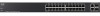
BYPASS LINK RX TX LINK RX TX Cisco SCE 2000 Series 4xGBE LINK RX TX LINK RX TX RX MM TX RX MM TX GBE-1 SUB LINE NET RX MM TX RX MM TX GBE-2 SUB LINE/CASCADE NET Port 1 subscriber Port 2 network Network 92798 Subscriber Router Router When configuring the SCE 2000 , an inline - Cisco SLM2024T-NA | Configuration Guide - Page 32
Cisco SCE 2000 Series 4xGBE LINK RX TX LINK RX TX RX MM TX RX MM TX GBE-1 SUB LINE NET RX MM TX RX MM TX GBE-2 SUB LINE/CASCADE NET 92799 Subscriber Router Link 2 Router Network This topology supports . Cisco SCE 2000 4xGBE Installation and Configuration Guide 3-6 OL-7824-06 - Cisco SLM2024T-NA | Configuration Guide - Page 33
switch, the switch must support SPAN functionality that includes separation between ingress and egress traffic and multiple SPAN-ports supports monitoring functionality only, and is configured as "receive-only" connection mode. OL-7824-06 Cisco SCE 2000 4xGBE Installation and Configuration Guide - Cisco SLM2024T-NA | Configuration Guide - Page 34
Cisco SCE 2000 Series 4xGBE LINK RX TX LINK RX TX LINK RX TX RX MM TX RX MM TX GBE-1 SUB LINE NET RX MM TX RX MM TX GBE-2 SUB LINE/CASCADE NET Link 2 92797 Subscriber Router Optical splitter Router Network Note When implementing receive-only topologies with a switch, the switch - Cisco SLM2024T-NA | Configuration Guide - Page 35
the line that goes through the failed SCE 2000 . In this case network redundancy protocols like HSRP are responsible for identifying the line cutoff and switching all the traffic to go through the functioning SCE 2000 . OL-7824-06 Cisco SCE 2000 4xGBE Installation and Configuration Guide 3-9 - Cisco SLM2024T-NA | Configuration Guide - Page 36
setup of the SCE 2000 . • SCE 2000 Configuration on the data link. Data is forwarded to the SCE 2000 via an external switch. The ports. The connection mode parameter is determined by the physical deployment of the SCE 2000 , as follows: 3-10 Cisco SCE 2000 4xGBE Installation and Configuration Guide - Cisco SLM2024T-NA | Configuration Guide - Page 37
supports a maximum of two links, which are designated link 0 and link 1. Priority In a cascade topology, the user must define the priority of each SCE 2000 . • Primary - The Primary SCE 2000 is active by default the bypass card supports four different modes. if value-added services are crucial and - Cisco SLM2024T-NA | Configuration Guide - Page 38
Information About Topology Considerations Chapter 3 Information About Topology 3-12 Cisco SCE 2000 4xGBE Installation and Configuration Guide OL-7824-06 - Cisco SLM2024T-NA | Configuration Guide - Page 39
, this chapter contains instructions for installing or replacing the power supply units and fan modules. Before you install, operate, or service the system, read the Regulatory Compliance and Safety Information for the Cisco Service Control Engine . This guide contains important safety information - Cisco SLM2024T-NA | Configuration Guide - Page 40
wire. • Level (optional) • Tape measure (optional) • Appropriate cables to connect the SCE 2000 to the network and console terminal • Rack-mounting kit (optional) • A new AC-input or DC-input power supply • A new fan module Cisco SCE 2000 4xGBE Installation and Configuration Guide 4-2 OL-7824-06 - Cisco SLM2024T-NA | Configuration Guide - Page 41
SCE 2000 and the layout of your equipment rack or wiring closet is essential for successful system operation / CONSOLE AUX PWR A PWR B STATUS BYPASS LINK RX TX LINK RX TX RX MM TX RX MM TX GBE-1 SUB LINE NET Cisco S4CxEG2B0E00 Cisco SCE 2000 4xGBE Installation and Configuration Guide 4-3 - Cisco SLM2024T-NA | Configuration Guide - Page 42
the Cisco Service Control Engine document. The DC-powered SCE 2000 should be installed in a Restricted Access Location only. Installing the SCE 2000 Platform The SCE 2000 operates as either a tabletop or a rack-mounted unit. A rack-mounting kit is included with the SCE 2000 when it is shipped from - Cisco SLM2024T-NA | Configuration Guide - Page 43
or in a rack, ensure that the surface is clean and in a safe location. Figure 4-3 Installing the System on a Flat Surface MNG 1 MNG 2 ALCITNIKV/E101/010000/ ALCITNIKV/E101/010000/ CONSOLE AUX PWR A PWR B STATUS BYPASS LINK RX TX RX MM TX LINK RX TX RX MM TX GBE-1 SUB LINE NET Cisco - Cisco SLM2024T-NA | Configuration Guide - Page 44
the bottom panel). 5. Replace the SCE 2000 platform firmly racks, and the appropriate brackets for each are provided in the enclosed kit. • 19" rack with front rack posts - the mounting kit includes two mounting brackets as illustrated below. Cisco SCE 2000 4xGBE Installation and Configuration Guide - Cisco SLM2024T-NA | Configuration Guide - Page 45
front and back rack posts - in addition to the mounting brackets illustrated below, the mounting kit includes two crossrail supports that the unit slides onto. Mounting Brackets for 2-post Rack Figure 4-4 Mounting Brackets for 4-post Rack Figure 4-5 210429 210430 The SCE 2000 mounts to the two - Cisco SLM2024T-NA | Configuration Guide - Page 46
1 and 2 on the other side of the SCE 2000 . This completes the steps for attaching the rack-mount brackets to the SCE 2000 . If mounting the SCE 2000 in a rack with only two posts, skip to How to Mount the System to the Rack. Cisco SCE 2000 4xGBE Installation and Configuration Guide 4-8 OL-7824-06 - Cisco SLM2024T-NA | Configuration Guide - Page 47
4 Align the crossrail supports with the side of the rack, parallel to the floor. Insert and tighten two screws to the front posts or mounting strips of the rack Insert and tighten two screws to the Back posts of the rack. OL-7824-06 Cisco SCE 2000 4xGBE Installation and Configuration Guide 4-9 - Cisco SLM2024T-NA | Configuration Guide - Page 48
2000 ) meet the mounting strips or posts on both sides of the rack. A rack with both front and back posts will have the crossrail supports installed. Slide the SCE 2000 onto these crossrails and push it all the way back. 4-10 Cisco SCE 2000 4xGBE Installation and Configuration Guide OL-7824-06 - Cisco SLM2024T-NA | Configuration Guide - Page 49
TX RX MM TX GBE-1 SUB LINE NET Cisco S4CxEG2B0E00 Series LINK RX TX LINK RX TX RX MM TX RX MM TX GBE-2 SUB LINE/CASCADE NET 92779 Step 5 For each bracket, insert and tighten two appropriate screws to the rack. OL-7824-06 Cisco SCE 2000 4xGBE Installation and Configuration Guide 4-11 - Cisco SLM2024T-NA | Configuration Guide - Page 50
support the weight of the entire SCE 2000 chassis, be sure to use all four screws to fasten the two rack-mount brackets to the rack Step 2 Step 3 From the enclosed grounding kit, remove the necessary materials - the grounding cable Cisco SCE 2000 4xGBE Installation and Configuration Guide OL-7824-06 - Cisco SLM2024T-NA | Configuration Guide - Page 51
Chapter 4 Installation and Maintenance Figure 4-12 Grounding the Unit (AC) BYPASS 1 IN POWER B OK IN POWER A OK 12 Installing the SCE 2000 Platform 210421 OL-7824-06 Cisco SCE 2000 4xGBE Installation and Configuration Guide 4-13 - Cisco SLM2024T-NA | Configuration Guide - Page 52
Power • How to Remove the Power Supply Unit Information About the Power Supply The SCE 2000 is available in two power options: • Dual line feed AC power - SCE 2000 is shipped with two appropriate AC power supply cords. 4-14 Cisco SCE 2000 4xGBE Installation and Configuration Guide OL-7824-06 - Cisco SLM2024T-NA | Configuration Guide - Page 53
and Maintenance Removing and Replacing a Power Supply Unit • Dual line feed DC power The faceplates of both power supplies have a handle, an on/off switch, and one captive installation screw. An AC-input power receptacle is available Cisco SCE 2000 4xGBE Installation and Configuration Guide 4-15 - Cisco SLM2024T-NA | Configuration Guide - Page 54
Removing and Replacing a Power Supply Unit Chapter 4 Installation and Maintenance • On the power supply unit (both AC-input and DC-input malfunctioning Corresponding power supply unit is either not present or has failed. 4-16 Cisco SCE 2000 4xGBE Installation and Configuration Guide OL-7824-06 - Cisco SLM2024T-NA | Configuration Guide - Page 55
Maintenance Removing and Replacing a Power Supply Unit Note Simple Network Management Protocol (SNMP) monitors the activity of the power supplies. In most cases when a power supply problem occurs, an SNMP trap is sent in SNMP and the appropriate message is posted on the SCE 2000 CLI. Power Supply - Cisco SLM2024T-NA | Configuration Guide - Page 56
power supply is being removed or replaced. SUMMARY STEPS 1. Place the on/off switch on the DC-input power switch providing power to the DC-input power supply. 3. Observe that the corresponding Power LED on the front panel turns off. 4-18 Cisco SCE 2000 4xGBE Installation and Configuration Guide - Cisco SLM2024T-NA | Configuration Guide - Page 57
Replace the Power Supply Unit DETAILED STEPS 4. Remove the screw from one DC power line input lead receptacle and pull the lead from the connector. Repeat this step for the remaining lead. Step 1 Step 2 Step 3 Step 4 Place the on/off switch or switch providing DC power line input to Replace the - Cisco SLM2024T-NA | Configuration Guide - Page 58
AC-input power receptacle on the AC-input power supply 2. Plug the AC power supply cable into the AC power source. 3. Turn the on/off switch to the on (¿) position. 4-20 Cisco SCE 2000 4xGBE Installation and Configuration Guide OL-7824-06 - Cisco SLM2024T-NA | Configuration Guide - Page 59
power supply unit is OFF, locate the circuit breaker on the panel board that services the DC circuit, switch the circuit breaker to the OFF position, and tape the switch handle of the circuit breaker in the OFF position. OL-7824-06 Cisco SCE 2000 4xGBE Installation and Configuration Guide 4-21 - Cisco SLM2024T-NA | Configuration Guide - Page 60
connector on one power line input, insert the screw with the connector into the corresponding lead receptacle and tighten the receptacle screw using the number 2 Phillips . Repeat for the remaining power line input lead. 4-22 Cisco SCE 2000 4xGBE Installation and Configuration Guide OL-7824-06 - Cisco SLM2024T-NA | Configuration Guide - Page 61
platform. When a fan malfunctions, the fan module should be replaced as promptly as possible. Although it is possible for the unit to function for some time with one non-functioning fan, this is not optimal or recommended. OL-7824-06 Cisco SCE 2000 4xGBE Installation and Configuration Guide 4-23 - Cisco SLM2024T-NA | Configuration Guide - Page 62
to the console. An SNMP replace a fan module in a SCE 2000 platform: Do not remove or install modules without using appropriate anti-static guard measures. The SCE 2000 includes an anti-static wrist strap in the accessory kit 24 Cisco SCE 2000 4xGBE Installation and Configuration Guide OL-7824-06 - Cisco SLM2024T-NA | Configuration Guide - Page 63
Module Overview Replacing the Fan Module SUMMARY STEPS 1. Grasp the fan module handle with one hand and place your other hand underneath the fan module for support. The handle of the unit should be at the bottom. 2. Fit the groove in the side of the new fan module into the guide in the - Cisco SLM2024T-NA | Configuration Guide - Page 64
is danger of explosion if the lithium battery is incorrectly replaced. Replace only with the same or equivalent type recommended by the manufacturer. Dispose of used batteries according to the manufacturer's instructions. 4-26 Cisco SCE 2000 4xGBE Installation and Configuration Guide OL-7824-06 - Cisco SLM2024T-NA | Configuration Guide - Page 65
to a local console and configure the initial settings for the SCE 2000 to support remote management. When the initial connection is established, the setup utility will run automatically, prompting you to perform the initial system configuration. This section provides instructions for setting up your - Cisco SLM2024T-NA | Configuration Guide - Page 66
the VT100 compatible local (serial) terminal. Make sure the local terminal is configured as a VT-100 terminal, according to the fixed SCE 2000 CON port parameters. Press Enter several times until the Cisco logo appears on the local terminal and the setup configuration dialog is entered. --- System - Cisco SLM2024T-NA | Configuration Guide - Page 67
system configuration wizard automatically runs to guide the user through the entire setup process. The wizard prompts for all necessary parameters, displaying default values, where applicable. You may accept the default values or define other values. With the exception of the time settings, which - Cisco SLM2024T-NA | Configuration Guide - Page 68
5 Connecting the Management Interfaces and Performing Initial System Configuration Setup Command Parameters Table 5-1 Setup Command Parameters Parameter IP address subnet mask default gateway Hostname admin password root password password encryption status Time Settings time zone name and - Cisco SLM2024T-NA | Configuration Guide - Page 69
System Configuration Table 5-1 Setup Command Parameters Parameter Definition Access Control List number How many ACLs will be necessary? What IP addresses will be permitted/denied access for each management interface? You may want ACLs for the following: • Any IP access • Telnet access - Cisco SLM2024T-NA | Configuration Guide - Page 70
: • IP address • Subnet mask • Default gateway All values are Internet addresses of the form 'X.X.X.X' , where each letter corresponds to a decimal number between 0 and 255. SUMMARY STEPS 1. The current IP address is displayed. Cisco SCE 2000 4xGBE Installation and Configuration Guide 5-6 OL - Cisco SLM2024T-NA | Configuration Guide - Page 71
it must be entered explicitly. Enter IP address [10.1.1.201]:10.1.5.109Enter IP subnet mask:255.255.0.0Enter IP address of default gateway [10.1.1.3]: Step 2: How to Configure the Hostname The hostname is used to identify the SCE 2000 . It appears as part of the CLI prompt and is also returned as - Cisco SLM2024T-NA | Configuration Guide - Page 72
sensitive. Note The default password for all levels is " cisco". SUMMARY STEPS DETAILED STEPS 1. The default User password is displayed. 2. The default Admin password is displayed. 3. The default Root password is displayed. 4. Configure password encryption. By default, password encryption is not - Cisco SLM2024T-NA | Configuration Guide - Page 73
changing all passwords. Password encryption is not enabled (default). Enter a User password [cisco]: userinEnter an Admin password [cisco]: mng123Enter a Root password [cisco]: cistechEnable passwords encryption? [no]: Step 4: How to Configure Time Settings The time settings menu configures all time - Cisco SLM2024T-NA | Configuration Guide - Page 74
no]: yEnable SNTP broadcast client? [no]: yEnter time interval in seconds between unicast updates [900]: Would you like to configure SNTP unicast servers? [no]: yEnter IP address or hostname of SNTP unicast server: 10.1.1.1 5-10 Cisco SCE 2000 4xGBE Installation and Configuration Guide OL-7824-06 - Cisco SLM2024T-NA | Configuration Guide - Page 75
the Management Interfaces and Performing Initial System Configuration Initial System Configuration Step 5: How to Configure the DNS Settings The DNS configuration menu defines the IP address of the domain name server, which is used for DNS lookup, as well as the default domain name, which - Cisco SLM2024T-NA | Configuration Guide - Page 76
's IP address: 10.1.1.230Enter RDR-formatter destination's TCP port number: 33000 Step 7: Configuring Access Control Lists (ACLs) The SCE 2000 can be configured with Access Control Lists (ACLs), which are used to permit or deny incoming connections on any of the management interfaces. 5-12 Cisco - Cisco SLM2024T-NA | Configuration Guide - Page 77
IP address. Refer to the table below for examples. Each range of IP addresses can be configured to be permitted or denied access. • Individual IP address - Type the desired IP address, then enter the wildcard bits 0.0.0.0. OL-7824-06 Cisco SCE 2000 4xGBE Installation and Configuration Guide - Cisco SLM2024T-NA | Configuration Guide - Page 78
you would like to create another ACL. You may define up to 99 ACLs. 9. Restrict IP access to the SCE 2000 by assigning the appropriate ACL. 10. Restrict Telnet access to the SCE 2000 by assigning the appropriate ACL. 5-14 Cisco SCE 2000 4xGBE Installation and Configuration Guide OL-7824-06 - Cisco SLM2024T-NA | Configuration Guide - Page 79
to create another ACL. You may define up to 99 ACLs. • To create another ACL, type y and press • Enter Would you like to configure another list? [no]: y Enter up to 20 IP addresses in this new ACL, as described in and . OL-7824-06 Cisco SCE 2000 4xGBE Installation and Configuration Guide 5-15 - Cisco SLM2024T-NA | Configuration Guide - Page 80
all IP addresses. • For Telnet - permit access to the specified IP address, and deny to all others. ACL #1 = permit any IP address. Assign to IP access. ACL #2 = permit access to 10.1.1.0, 10.10.10.1, deny to all others. Assign to Telnet access. Would you like to enter the Access lists configuration - Cisco SLM2024T-NA | Configuration Guide - Page 81
Assign an access list to restrict the SNMP management stations that may use this SET community. 8. The maximum number of SET communities is 20. 9. Enter the SNMP trap managers menu. 10. Type the trap manager IP address and press Enter. 11. Type the trap manager community string and press Enter. 12 - Cisco SLM2024T-NA | Configuration Guide - Page 82
manager IP address and press Enter. Enter SNMP trap manager IP address: Note that there is no default for this parameter. Type the trap manager community string and press Enter. Note that there is no default for this parameter. 5-18 Cisco SCE 2000 4xGBE Installation and Configuration Guide OL - Cisco SLM2024T-NA | Configuration Guide - Page 83
this community string, use '0' to allow all: 2Would you like to add another SNMP SET community? [no]: Would you like to configure SNMP trap managers? [no]: yEnter SNMP trap manager IP address: 10.1.1.253Enter SNMP trap manager community string: publicEnter trap manager SNMP version: 2cWould you like - Cisco SLM2024T-NA | Configuration Guide - Page 84
mode after abnormal (not user-requested) boot, or stays in non-operational mode, in which the SCE 2000 behaves as in failure mode. This parameter can be set to one of the following: - Operational - Non-operational 5-20 Cisco SCE 2000 4xGBE Installation and Configuration Guide OL-7824-06 - Cisco SLM2024T-NA | Configuration Guide - Page 85
: 0- link-0 1- link-1 Enter your choice [0]: Specify the SCE 2000 priority. • To specify Primary , press Enter. • To specify Secondary , type 2and press Enter. OL-7824-06 Cisco SCE 2000 4xGBE Installation and Configuration Guide 5-21 - Cisco SLM2024T-NA | Configuration Guide - Page 86
is specified, the user must specify the on-failure link behavior. Would you like to enter the Topology configuration menu? [no ports (ports 3 and 4). Each SCE 2000 is connected inline to both sides (subscribers/network) of one GBE link. 5-22 Cisco SCE 2000 4xGBE Installation and Configuration Guide - Cisco SLM2024T-NA | Configuration Guide - Page 87
to view them. Press Enter. Found errors in the new configuration, would you like to view them? [yes]: The following errors were found: Warning - RDR formatter destination 10.1.1.1 is not allowed in the IP access-class. OL-7824-06 Cisco SCE 2000 4xGBE Installation and Configuration Guide 5-23 - Cisco SLM2024T-NA | Configuration Guide - Page 88
not allowed in the IP access-class. Warning - default Gateway 10.1.1.1 is not allowed in the IP access-class. Warning - IP Access list (1) conflicts with Telnet Access list (2) as follows: Access list 2 permits all addresses while Access list 1 denies it. Apply and Save this configuration? [yes/no - Cisco SLM2024T-NA | Configuration Guide - Page 89
used, they must both be connected to the management console via a switch. In this way, the IP address of the MNG port is always the same, regardless of which physical port is currently active. The procedures for cabling the management port and testing connectivity between the SCE 2000 and the remote - Cisco SLM2024T-NA | Configuration Guide - Page 90
the relevant Mng port LEDS. 2. Test connectivity. From the host that you intend to use for remote management, ping to the SCE 2000 by typing ping and the SCE 2000 IP address, and pressing Enter (see the example, below). 5-26 Cisco SCE 2000 4xGBE Installation and Configuration Guide OL-7824-06 - Cisco SLM2024T-NA | Configuration Guide - Page 91
The state of the 10/100/1000 LED will depend on the Ethernet network settings. Green indicates 100 Mbps and 'Off' indicates 10 Mbps. Test connectivity. From the host that you intend to use for remote management, ping to the SCE 2000 by typing ping and the SCE 2000 IP address, and pressing Enter (see - Cisco SLM2024T-NA | Configuration Guide - Page 92
Connecting the Management Interface Chapter 5 Connecting the Management Interfaces and Performing Initial System Configuration 5-28 Cisco SCE 2000 4xGBE Installation and Configuration Guide OL-7824-06 - Cisco SLM2024T-NA | Configuration Guide - Page 93
This chapter provides instructions for cabling the Gigabit Ethernet ports for both one and two SCE 2000 topologies, and for configuring Gigabit Ethernet (GBE) interface parameters. In a topology utilizing two SCE 2000 s (cascade), this includes the cascade ports as well as the line ports. Note When - Cisco SLM2024T-NA | Configuration Guide - Page 94
SCE 2000 . Note Receive-only topologies can also be implemented using a switch. Such a switch must support SPAN functionality that includes separation between ingress and egress traffic and multiple SPAN-ports destinations. Cisco SCE 2000 4xGBE Installation and Configuration Guide 6-2 OL-7824-06 - Cisco SLM2024T-NA | Configuration Guide - Page 95
between ingress and egress traffic and multiple SPAN-ports destinations. The following two diagrams illustrate the connections for dual links, with a single SCE 2000 deployed for both inline and receive-only topologies. OL-7824-06 Cisco SCE 2000 4xGBE Installation and Configuration Guide 6-3 - Cisco SLM2024T-NA | Configuration Guide - Page 96
2 PWR A PWR B STATUS BYPASS LINK RX TX LINK RX TX Cisco SCE 2000 Series 4xGBE LINK RX TX LINK RX TX RX MM TX RX MM TX GBE-1 SUB LINE NET RX MM TX RX MM TX GBE-2 SUB LINE/CASCADE NET Network 1 Network 2 92785 Cisco SCE 2000 4xGBE Installation and Configuration Guide 6-4 OL-7824-06 - Cisco SLM2024T-NA | Configuration Guide - Page 97
both Receive and Transmit fibers to the SCE 2000 . Cascade ports always require both Receive and Transmit fibers to be connected. The following diagram illustrates the connections for a dual link, two SCE 2000 inline topology OL-7824-06 Cisco SCE 2000 4xGBE Installation and Configuration Guide 6-5 - Cisco SLM2024T-NA | Configuration Guide - Page 98
cascading PWR A PWR B STATUS BYPASS LINK RX TX LINK RX TX Cisco SCE 2000 Series 4xGBE LINK RX TX LINK RX TX RX MM TX RX MM TX GBE-1 SUB LINE NET RX MM TX RX MM TX GBE-2 SUB LINE/CASCADE NET Network 2 92788 Cisco SCE 2000 4xGBE Installation and Configuration Guide 6-6 OL-7824-06 - Cisco SLM2024T-NA | Configuration Guide - Page 99
the Installation Connecting the line ports to the network How to Configure the GBE Interface Parameters By default, the SCE 2000 GBE line interface ports are configured with auto-negotiation disabled. The procedure for enabling auto-negotiation for the GBE line interface ports is explained in the - Cisco SLM2024T-NA | Configuration Guide - Page 100
line ports are connected to the module. See The External Optical Bypass Module for complete instructions 50µm Core Diameter MMF • 400m for 62.5µm Core Diameter MMF 10 km for 9.0µm Core Diameter SMF SUMMARY STEPS 1. Take the Cisco SCE 2000 4xGBE Installation and Configuration Guide 6-8 OL-7824-06 - Cisco SLM2024T-NA | Configuration Guide - Page 101
. The Tx LEDs do not "blink", since the Tx is not connected to the port in this topology. How to View the Gigabit Ethernet Port Status Step 1 At the SCE 2000# prompt, type show interfaceGigabitEthernet 0/ interface-number. OL-7824-06 Cisco SCE 2000 4xGBE Installation and Configuration Guide 6-9 - Cisco SLM2024T-NA | Configuration Guide - Page 102
following example shows the counters of the first Gigabit Ethernet interface. SCE 2000#show interface GigabitEthernet 0/1 counters In total octets: 100 In good unicast packets: 90 In good multicast packets: 0 In good broadcast packets: 10 In packets discarded: 0 In packets with CRC/Alignment error - Cisco SLM2024T-NA | Configuration Guide - Page 103
(See Connecting the Management Interfaces and Performing Initial System Configuration.) 3. Connect the cascade ports. The cascade ports must be connected directly in Layer 1 (dark fibers), not through switches. (See Dual Link: Two SCE 2000s Topology.) 4. Set topology configurations for each SCE 2000 - Cisco SLM2024T-NA | Configuration Guide - Page 104
. (See Connecting the Management Interfaces and Performing Initial System Configuration.) Connect the cascade ports. The cascade ports must be connected directly in Layer 1 (dark fibers), not through switches. (See Dual Link: Two SCE 2000s Topology.) Set topology configurations for each SCE 2000 - Cisco SLM2024T-NA | Configuration Guide - Page 105
Line Ports Configure the Connection Mode Use the following command to configure the EXAMPLE 1 Use the following command to configure the primary SCE platform in a EXAMPLE 2 Use the following command to configure the SCE platform that might on-failure bypass How to Set the Link Mode The SCE platform - Cisco SLM2024T-NA | Configuration Guide - Page 106
the System Use the following commands to view the current connection mode and link mode parameters. • How to View the Current Connection Mode • How to View the Current Link Mode • How to View the Current Link Mappings 6-14 Cisco SCE 2000 4xGBE Installation and Configuration Guide OL-7824-06 - Cisco SLM2024T-NA | Configuration Guide - Page 107
the Line Ports and Completing the Installation How to Load and Activate a Service Control manual. For further details, refer to the following documentation: • Service Control Application for Broadband User Guide • Service Control Application for Broadband Reference Guide OL-7824-06 Cisco - Cisco SLM2024T-NA | Configuration Guide - Page 108
How to Load and Activate a Service Control Application Chapter 6 Cabling the Line Ports and Completing the Installation 6-16 Cisco SCE 2000 4xGBE Installation and Configuration Guide OL-7824-06 - Cisco SLM2024T-NA | Configuration Guide - Page 109
Subsequent startups - Line and Cascade interfaces are properly cabled (optional) - SCE 2000 platform is connected to at least one of the following types of management stations: - Direct connection to local console (CON port) OL-7824-06 Cisco SCE 2000 4xGBE Installation and Configuration Guide 7-1 - Cisco SLM2024T-NA | Configuration Guide - Page 110
this publication. For further information on system and interface configuration, refer to the following documents: • Cisco Service Control Engine (SCE) Software Configuration Guide • Cisco Service Control Engine (SCE) CLI Command Reference Starting the System and Observing Initial Conditions After - Cisco SLM2024T-NA | Configuration Guide - Page 111
console screen displays a script and system banner similar to the following: Cisco setup wizard to configure the system, or exiting from setup and using configuration commands to configure global (system-wide) and interface-specific parameters. You do not have to configure the interfaces - Cisco SLM2024T-NA | Configuration Guide - Page 112
platform is up. After reboot, the SCE platform loads the startup-config , which includes the non-default configuration as saved by the user, into the running-config . The SCE platform provides commands for: • Viewing the running configuration • Viewing the startup configuration Cisco SCE 2000 4xGBE - Cisco SLM2024T-NA | Configuration Guide - Page 113
active no silent no shutdown flow-aging default-timeout UDP 60 interface FastEthernet 0/0 ip address 10.1.5.109 255.255.0.0 interface FastEthernet 0/1 interface FastEthernet 0/2 exit line vty 0 4 no timeout exit SCE 2000# How to Save or Change the Configuration Settings When you make changes to the - Cisco SLM2024T-NA | Configuration Guide - Page 114
no shutdown flow-aging default-timeout UDP 60 interface FastEthernet 0/0 ip address 10.1.5.109 255.255.0.0 interface FastEthernet 0/1 interface FastEthernet 0/2 exit line vty 0 4 no timeout exit SCE 2000# SCE 2000#copy running-config startup-configWriting general configuration file to temporary - Cisco SLM2024T-NA | Configuration Guide - Page 115
on 19:36:07 UTC THU February 14 2006 #cli-type 1 #version 1 interface LineCard 0 no silent no shutdown interface FastEthernet 0/0 ip address 10.1.5.109 255.255.0.0 interface FastEthernet 0/1 interface FastEthernet 0/2 exit OL-7824-06 Cisco SCE 2000 4xGBE Installation and Configuration Guide 7-7 - Cisco SLM2024T-NA | Configuration Guide - Page 116
Platform: SCE 2000 - 4xGBE Management agent interface version: SCE Agent 3.0.5 Build 18 Software package file: ftp://vk:[email protected]/P:/EMB/LatestVersion/3.0.5/se1000.pkg SCE 2000 uptime is 21 minutes, 37 seconds SCE 2000# Cisco SCE 2000 4xGBE Installation and Configuration Guide 7-8 OL-7824-06 - Cisco SLM2024T-NA | Configuration Guide - Page 117
MIB (see Final Tests in the Cisco Service Control Engine (SCE) Software Configuration Guide ) • CLI show inventorycommand The show inventoryCLI command displays the following information: • Device name • Description • Product identifier • Version identifier • Serial number Step 1 From the SCE 2000 - Cisco SLM2024T-NA | Configuration Guide - Page 118
running configuration before performing reload, as described in How to Save or Change the Configuration Settings. SUMMARY STEPS 1. Connect to the serial console port (The CON connector on the SCE platform front panel, 9600 baud). 7-10 Cisco SCE 2000 4xGBE Installation and Configuration Guide OL - Cisco SLM2024T-NA | Configuration Guide - Page 119
command can only be executed from the serial CLI console. This limitation helps prevent situations in which a user issues this command from a Telnet session, and then realizes he/she has no physical access to the SCE platform. OL-7824-06 Cisco SCE 2000 4xGBE Installation and Configuration Guide - Cisco SLM2024T-NA | Configuration Guide - Page 120
Rebooting and Shutting Down the SCE Platform Chapter 7 Basic SCE 2000 Platform Operations 7-12 Cisco SCE 2000 4xGBE Installation and Configuration Guide OL-7824-06 - Cisco SLM2024T-NA | Configuration Guide - Page 121
. Table 8-1 Troubleshooting Strategy for Startup Problems Step 1 Step 2 Action Yes Turn power on. Go to Step 2 Power A/Power B LEDs Go to Step 3 on? No Refer to Troubleshooting the Power Subsystem and go to Step 3. OL-7824-06 Cisco SCE 2000 4xGBE Installation and Configuration Guide 8-1 - Cisco SLM2024T-NA | Configuration Guide - Page 122
Cisco Service Control Engine (SCE) CLI Command Reference for more information. Note Remember that if the management interface is not operational, you should connect the SCE 2000 platform to a local console so that you can enter CLI commands for troubleshooting. • Troubleshooting firmware package - Cisco SLM2024T-NA | Configuration Guide - Page 123
from the show line vty timeout command. Timeout is 30 minutes • Troubleshooting the link interface subsystem: - show interface GigabitEthernet 0/#- Displays information for a specific GBE Interface. Following is a sample output from the show interface command. ip address: 10.1.6.145 subnet mask - Cisco SLM2024T-NA | Configuration Guide - Page 124
: 0 Out non unicast packets: 0 Out packets discarded: 0 Refer to Troubleshooting with the User Log for an explanation of commands related to the user log. Checking the LEDs The front panel LEDS are the most immediate problem-detection mechanism of the platform. Refer to the following sections for - Cisco SLM2024T-NA | Configuration Guide - Page 125
mode consequent to failure-induced reboot (this is configurable using CLI command) Note Depending on the cause of failure, the management interface and the platform configuration may or may not be active/available. Red OL-7824-06 Cisco SCE 2000 4xGBE Installation and Configuration Guide 8-5 - Cisco SLM2024T-NA | Configuration Guide - Page 126
descriptions to isolate the problem to a subsystem, and then proceed to the appropriate sections to try to resolve the problem. When you start up the system by turning on the power supply switch, the following should occur: Cisco SCE 2000 4xGBE Installation and Configuration Guide 8-6 OL-7824-06 - Cisco SLM2024T-NA | Configuration Guide - Page 127
to the console port. • If the banner is displayed, but the Status LED is flashing orange, indicating a warning state, check the user log: At the prompt, type: more user log If any of the following warning messages appear, turn the SCE 2000 platform off and call technical support. - "voltage problem - Cisco SLM2024T-NA | Configuration Guide - Page 128
• Wrong file type. • Device to which the file is to be extracted is full. Table 8-5 Troubleshooting the Firmware Package Installation Diagnostic Action Enter the CLI command: • configure • Boot system Symptom Returned error is: Error-File does not exist In the output - Cisco SLM2024T-NA | Configuration Guide - Page 129
you to solve the problem and then reconnect through the management port. Table 8-6 Troubleshooting the Management Subsystem Symptom Diagnostic Action Management link down: • Mng LINK LED not lit • Status is WARNING (Status LED is flashing orange) • CLI command show interface Mng • ping to - Cisco SLM2024T-NA | Configuration Guide - Page 130
may be wrong: • IP address / subnet mask • IP default gateway See Connecting the Management Interfaces and Performing Initial System Configuration Refer to " IP Configuration " in the Cisco Service Control Engine (SCE) Software Configuration Guide. CLI command show access-lists An ACL - Cisco SLM2024T-NA | Configuration Guide - Page 131
Cisco Service Control Engine (SCE) Software Configuration Guide CLI commands: • show line • show line vty timeout Telnet connection may be timing out. Reconfigure line timeout. timeout Troubleshooting the Link Interface Subsystem Check the following to help isolate a problem - Cisco SLM2024T-NA | Configuration Guide - Page 132
incrementing, this indicates LED problem. Contact customer support. Check Cabling the Line Ports and Completing the Installation configurati on in the SCE 2000 and in peer. Check configuration in the SCE 2000 and in peer. 8-12 Cisco SCE 2000 4xGBE Installation and Configuration Guide OL-7824-06 - Cisco SLM2024T-NA | Configuration Guide - Page 133
to an external source. This command copies both log files to any external host running a FTP server. Step 1 From the SCE 2000# prompt, type logger get user-log file-nameftp://username:password@ipaddress/pathand press Enter. OL-7824-06 Cisco SCE 2000 4xGBE Installation and Configuration Guide 8-13 - Cisco SLM2024T-NA | Configuration Guide - Page 134
y and press Enter. DETAILED STEPS Step 1 Step 2 Step 3 From the SCE 2000# prompt, type clear logger device user-file-log and press Enter. The system asks Are you sure? Type yand press Enter. The SCE 2000# prompt appears. 8-14 Cisco SCE 2000 4xGBE Installation and Configuration Guide OL-7824-06 - Cisco SLM2024T-NA | Configuration Guide - Page 135
1 From the SCE 2000# prompt, type logger get support-filefilenameand press Enter. The support information file is created using the specified filename, and the SCE 2000# prompt appears. This operation may take some time. OL-7824-06 Cisco SCE 2000 4xGBE Installation and Configuration Guide 8-15 - Cisco SLM2024T-NA | Configuration Guide - Page 136
Troubleshooting with the User Log Chapter 8 Troubleshooting 8-16 Cisco SCE 2000 4xGBE Installation and Configuration Guide OL-7824-06 - Cisco SLM2024T-NA | Configuration Guide - Page 137
Bypass module enables the implementation of such replacement while preserving normal operation of the network link. The External Optical Bypass module is another important component in the Cisco overall carrier-grade solution for high-availability service provider networks • External Optical Bypass - Cisco SLM2024T-NA | Configuration Guide - Page 138
data link traffic - GBE connections from the External Optical Bypass module to one pair of the GBE line ports. creating a shortcut between the SCE 2000 platform GBE interfaces. The External Optical Bypass Module Front Panel The Cisco SCE 2000 4xGBE Installation and Configuration Guide A-2 OL-7824-06 - Cisco SLM2024T-NA | Configuration Guide - Page 139
in a 19" rack. Note that, although each module is shipped with its own mounting panel, it is not necessary to install each module in a separate mounting panel. Up to three modules may be installed in one mounting panel. OL-7824-06 Cisco SCE 2000 4xGBE Installation and Configuration Guide A-3 - Cisco SLM2024T-NA | Configuration Guide - Page 140
mounting panel. Secure the module panel to the two front posts of the rack -1 Line ports on kit) from the Bypass 9-pin D-Type connector on the rear panel of the SCE 2000 platform to the Control connector on the External Optical Bypass module. Cisco SCE 2000 4xGBE Installation and Configuration Guide - Cisco SLM2024T-NA | Configuration Guide - Page 141
of the SCE 2000 platform, as well as the GBE interfaces of the switch/router on either side of the External Optical Bypass module, be configured to Auto-Negotiation = OFF Connect the control cable (supplied in the kit) from the Bypass 9-pin D-Type connector on the rear panel of the SCE 2000 - Cisco SLM2024T-NA | Configuration Guide - Page 142
Installing the External Bypass Module Appendix A The External Optical Bypass Module Cisco SCE 2000 4xGBE Installation and Configuration Guide A-6 OL-7824-06
-
 1
1 -
 2
2 -
 3
3 -
 4
4 -
 5
5 -
 6
6 -
 7
7 -
8
-
9
-
10
-
11
-
12
-
13
-
14
-
15
-
16
-
17
-
18
-
19
-
20
-
21
-
22
-
23
-
24
-
25
-
26
-
27
-
28
-
29
-
30
-
31
-
32
-
33
-
34
-
35
-
36
-
37
-
38
-
39
-
40
-
41
-
42
-
43
-
44
-
45
-
46
-
47
-
48
-
49
-
50
-
51
-
52
-
53
-
54
-
55
-
56
-
57
-
58
-
59
-
60
-
61
-
62
-
63
-
64
-
65
-
66
-
67
-
68
-
69
-
70
-
71
-
72
-
73
-
74
-
75
-
76
-
77
-
78
-
79
-
80
-
81
-
82
-
83
-
84
-
85
-
86
-
87
-
88
-
89
-
90
-
91
-
92
-
93
-
94
-
95
-
96
-
97
-
98
-
99
-
100
-
101
-
102
-
103
-
104
-
105
-
106
-
107
-
108
-
109
-
110
-
111
-
112
-
113
-
114
-
115
-
116
-
117
-
118
-
119
-
120
-
121
-
122
-
123
-
124
-
125
-
126
-
127
-
128
-
129
-
130
-
131
-
132
-
133
-
134
-
135
-
136
-
137
-
138
-
139
-
140
-
141
-
142
 |
 |

Americas Headquarters
Cisco Systems, Inc.
170 West Tasman Drive
San Jose, CA 95134-1706
USA
Tel: 408 526-4000
800 553-NETS (6387)
Fax: 408 527-0883
Cisco SCE 2000 4xGBE Installation and
Configuration Guide
Release 3.1
May 2007
Text Part Number: OL-7824-06