Cisco WS-C3560-8PC-S Installation Guide - Page 158
B-3, B-5, B-6, C-2, C-4
 |
UPC - 882658120404
View all Cisco WS-C3560-8PC-S manuals
Add to My Manuals
Save this manual to your list of manuals |
Page 158 highlights
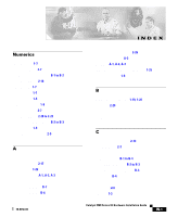
Index See RPS regulatory statements, EMC 2-5 RJ-45 connector, console port 2-24, B-3 RJ-45 console port 1-21 rollover cable 2-24, B-5, B-6 RPS connecting to 2-17 connector 1-23 LED 1-15 warning C-2, C-4 S safety 2-2, C-1 SC connector 2-21, B-2 to B-3 security values 2-31 setup program 2-25 to 2-28 shelf-mounting 2-17 shock hazard warning C-41 slots See ports 1-9 SNMP network management platforms 1-3, 1-25 software by model 1-2 software switch management 1-24 specifications A-1 stacking the chassis warning C-13 standard edition software, switches running 1-2 startup powering on 2-17 straight-through cable pinouts B-4 SunNet Manager 1-25 supply circuit warning C-24 switch applications 1-25 startup powering on 2-17 system LED 1-14 T table-mounting 2-17 technical specifications A-1 Telnet, and accessing the CLI 1-25 temperature operating A-1 warning C-16 terminal, connecting to switch 2-23 terminal emulation software 2-23 TN power warning C-19 translated warnings C-1 troubleshooting 3-1 to 3-5 U UTL LED 1-16, 1-17 IN-6 Catalyst 3500 Series XL Hardware Installation Guide 78-6456-04
-
 1
1 -
2
-
3
-
4
-
5
-
6
-
7
-
8
-
9
-
10
-
11
-
12
-
13
-
14
-
15
-
16
-
17
-
18
-
19
-
20
-
21
-
22
-
23
-
24
-
25
-
26
-
27
-
28
-
29
-
30
-
31
-
32
-
33
-
34
-
35
-
36
-
37
-
38
-
39
-
40
-
41
-
42
-
43
-
44
-
45
-
46
-
47
-
48
-
49
-
50
-
51
-
52
-
53
-
54
-
55
-
56
-
57
-
58
-
59
-
60
-
61
-
62
-
63
-
64
-
65
-
66
-
67
-
68
-
69
-
70
-
71
-
72
-
73
-
74
-
75
-
76
-
77
-
78
-
79
-
80
-
81
-
82
-
83
-
84
-
85
-
86
-
87
-
88
-
89
-
90
-
91
-
92
-
93
-
94
-
95
-
96
-
97
-
98
-
99
-
100
-
101
-
102
-
103
-
104
-
105
-
106
-
107
-
108
-
109
-
110
-
111
-
112
-
113
-
114
-
115
-
116
-
117
-
118
-
119
-
120
-
121
-
122
-
123
-
124
-
125
-
126
-
127
-
128
-
129
-
130
-
131
-
132
-
133
-
134
-
135
-
136
-
137
-
138
-
139
-
140
-
141
-
142
-
143
-
144
-
145
-
146
-
147
-
148
-
149
-
150
-
151
-
152
-
 153
153 -
 154
154 -
 155
155 -
 156
156 -
 157
157 -
 158
158 -
 159
159 -
 160
160
 |
 |