Cisco WS-C3560-8PC-S Installation Guide - Page 31
/100 Ports, Catalyst 3524-PWR XL Switch - meter
 |
UPC - 882658120404
View all Cisco WS-C3560-8PC-S manuals
Add to My Manuals
Save this manual to your list of manuals |
Page 31 highlights
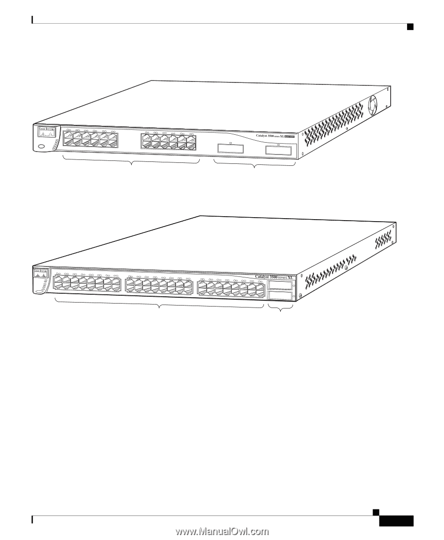
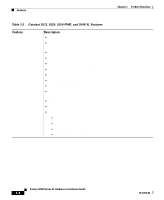
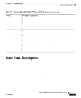
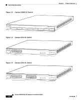
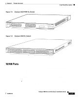
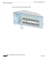
Chapter 1 Product Overview Figure 1-5 Catalyst 3524-PWR XL Switch Front-Panel Description 30291 12 1X 34 56 78 MODE SYSTEM RPS STATUS 2X DUPLX SPEED LINE PWR 9 10 11 12 11X 12X 13 14 13X 15 16 17 18 19 20 21 22 23 24 23X 14X 24X 10/100 inline-power ports Figure 1-6 Catalyst 3548 XL Switch 1 2 GBIC module slots 28010 SYSTEM RPS 12 1X 34 56 78 9 10 11 12 13 14 15 16 15X 17 18 17X 19 20 21 22 23 24 25 26 27 28 29 30 31 32 31X 33 34 33X 35 36 37 38 39 40 41 42 43 44 45 46 47 48 STATUS UTIL DUPLX SPEED 2X 47X 1 MODE 16X 18X 32X 34X 2 48X 10/100 ports GBIC module slots 10/100 Ports The 10/100 ports on the Catalyst 3512, 3524, 3524-PWR, and 3548 XL switches are grouped in pairs. For example, in Figure 1-3, Figure 1-4, Figure 1-5, and Figure 1-6, ports 1 and 2 are the left-most pair. The first member of the pair (port 1) is above the second member (port 2). Port 3 is above port 4, and so on. The 10/100 switch ports can connect, up to a distance of 100 meters, to any compatible network device: • 10BaseT-compatible devices such as workstations, Cisco IP Phones, and hubs through standard RJ-45 connectors and Category 3, 4, or 5 cabling 78-6456-04 Catalyst 3500 Series XL Hardware Installation Guide 1-7
-
 1
1 -
2
-
3
-
4
-
5
-
6
-
7
-
8
-
9
-
10
-
11
-
12
-
13
-
14
-
15
-
16
-
17
-
18
-
19
-
20
-
21
-
22
-
23
-
24
-
25
-
 26
26 -
 27
27 -
 28
28 -
 29
29 -
 30
30 -
 31
31 -
 32
32 -
 33
33 -
 34
34 -
 35
35 -
 36
36 -
37
-
38
-
39
-
40
-
41
-
42
-
43
-
44
-
45
-
46
-
47
-
48
-
49
-
50
-
51
-
52
-
53
-
54
-
55
-
56
-
57
-
58
-
59
-
60
-
61
-
62
-
63
-
64
-
65
-
66
-
67
-
68
-
69
-
70
-
71
-
72
-
73
-
74
-
75
-
76
-
77
-
78
-
79
-
80
-
81
-
82
-
83
-
84
-
85
-
86
-
87
-
88
-
89
-
90
-
91
-
92
-
93
-
94
-
95
-
96
-
97
-
98
-
99
-
100
-
101
-
102
-
103
-
104
-
105
-
106
-
107
-
108
-
109
-
110
-
111
-
112
-
113
-
114
-
115
-
116
-
117
-
118
-
119
-
120
-
121
-
122
-
123
-
124
-
125
-
126
-
127
-
128
-
129
-
130
-
131
-
132
-
133
-
134
-
135
-
136
-
137
-
138
-
139
-
140
-
141
-
142
-
143
-
144
-
145
-
146
-
147
-
148
-
149
-
150
-
151
-
152
-
153
-
154
-
155
-
156
-
157
-
158
-
159
-
160
 |
 |