Cisco WS-C3560-8PC-S Installation Guide - Page 40
Port LEDs and Modes, Color, RPS Status, Mode LED, Port Mode, Description
 |
UPC - 882658120404
View all Cisco WS-C3560-8PC-S manuals
Add to My Manuals
Save this manual to your list of manuals |
Page 40 highlights
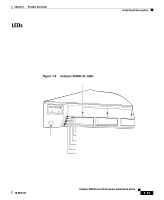
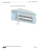
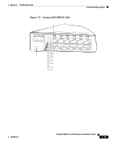
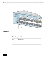
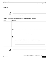
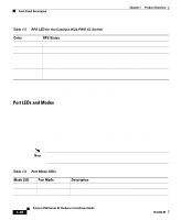
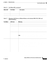
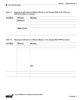
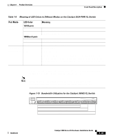
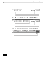
Front-Panel Description Chapter 1 Product Overview Table 1-5 RPS LED for the Catalyst 3524-PWR XL Switch Color Off Solid green Blinking green Solid amber Blinking amber RPS Status RPS is off or is not installed. RPS is connected and operational. RPS is backing up another switch in the stack. RPS is connected but not functioning properly. One of the power supplies in the RPS could be powered down, or a fan on the RPS could have failed. Internal power supply of the switch is down, and redundancy is lost. The switch is operating on the RPS. For more information about the failure conditions on the Cisco RPS 300, refer to the Cisco Redundant Power System 300 Hardware Installation Guide. Port LEDs and Modes Each 10/100 port and module slot has a port LED. These port LEDs, as a group or individually, display information about the switch and about the individual ports. The port modes (Table 1-6) determine the type of information displayed through the port LEDs. To select or change a mode, press the Mode button until the desired mode is highlighted. When you change port modes, the meaning of the port LED colors also changes. Table 1-7 and Table 1-8 explain how to interpret the port LED colors after you change the port mode. Note To change the port mode in the Catalyst 3548 XL switch, press the Mode label. Table 1-6 Port Mode LEDs Mode LED STAT UTL Port Mode Port status Switch utilization Description The port status. This is the default mode. The current bandwidth in use by the switch. 1-16 Catalyst 3500 Series XL Hardware Installation Guide 78-6456-04
-
 1
1 -
2
-
3
-
4
-
5
-
6
-
7
-
8
-
9
-
10
-
11
-
12
-
13
-
14
-
15
-
16
-
17
-
18
-
19
-
20
-
21
-
22
-
23
-
24
-
25
-
26
-
27
-
28
-
29
-
30
-
31
-
32
-
33
-
34
-
 35
35 -
 36
36 -
 37
37 -
 38
38 -
 39
39 -
 40
40 -
 41
41 -
 42
42 -
 43
43 -
 44
44 -
 45
45 -
46
-
47
-
48
-
49
-
50
-
51
-
52
-
53
-
54
-
55
-
56
-
57
-
58
-
59
-
60
-
61
-
62
-
63
-
64
-
65
-
66
-
67
-
68
-
69
-
70
-
71
-
72
-
73
-
74
-
75
-
76
-
77
-
78
-
79
-
80
-
81
-
82
-
83
-
84
-
85
-
86
-
87
-
88
-
89
-
90
-
91
-
92
-
93
-
94
-
95
-
96
-
97
-
98
-
99
-
100
-
101
-
102
-
103
-
104
-
105
-
106
-
107
-
108
-
109
-
110
-
111
-
112
-
113
-
114
-
115
-
116
-
117
-
118
-
119
-
120
-
121
-
122
-
123
-
124
-
125
-
126
-
127
-
128
-
129
-
130
-
131
-
132
-
133
-
134
-
135
-
136
-
137
-
138
-
139
-
140
-
141
-
142
-
143
-
144
-
145
-
146
-
147
-
148
-
149
-
150
-
151
-
152
-
153
-
154
-
155
-
156
-
157
-
158
-
159
-
160
 |
 |