Cisco WS-C3560-8PC-S Installation Guide - Page 43
Bandwidth Utilization for the Catalyst 3508G XL Switch, Table 1-8
 |
UPC - 882658120404
View all Cisco WS-C3560-8PC-S manuals
Add to My Manuals
Save this manual to your list of manuals |
Page 43 highlights
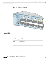
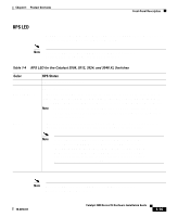
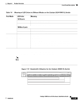
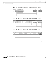
Chapter 1 Product Overview Front-Panel Description Table 1-8 Meaning of LED Colors in Different Modes on the Catalyst 3524-PWR XL Switch Port Mode LED Color SPEED (speed) 10/100 ports Off Green 1000BaseX ports Off Green LINE PWR Off (inline power) Green Meaning Port is operating at 10 Mbps. Port is operating at 100 Mbps. Port is not operating. Port is operating at 1000 Mbps. Inline power is off. Inline power is on. If the Cisco IP Phone is receiving power from an AC power source, the port LED is off even if the IP phone is connected to the switch port. The LED turns green only when the switch port is providing power. Figure 1-13, Figure 1-14, Figure 1-15, and Figure 1-16 show the bandwidth utilization percentages displayed by the right-most LEDs. Note The port LEDs on the Catalyst 3524-PWR XL switch do not show bandwidth utilization. To find out the switch bandwidth usage, use the Device Bandwidth Graph on VSM. Figure 1-13 Bandwidth Utilization for the Catalyst 3508G XL Switch 1 MODE SYSTEM RPS STATUS UTIL DUPLX SPEED 2 3 4 5 Catalyst 3500 XL 6 7 8 < 25% 25% - 49% + 50% + 22006 78-6456-04 Catalyst 3500 Series XL Hardware Installation Guide 1-19
-
 1
1 -
2
-
3
-
4
-
5
-
6
-
7
-
8
-
9
-
10
-
11
-
12
-
13
-
14
-
15
-
16
-
17
-
18
-
19
-
20
-
21
-
22
-
23
-
24
-
25
-
26
-
27
-
28
-
29
-
30
-
31
-
32
-
33
-
34
-
35
-
36
-
37
-
 38
38 -
 39
39 -
 40
40 -
 41
41 -
 42
42 -
 43
43 -
 44
44 -
 45
45 -
 46
46 -
 47
47 -
 48
48 -
49
-
50
-
51
-
52
-
53
-
54
-
55
-
56
-
57
-
58
-
59
-
60
-
61
-
62
-
63
-
64
-
65
-
66
-
67
-
68
-
69
-
70
-
71
-
72
-
73
-
74
-
75
-
76
-
77
-
78
-
79
-
80
-
81
-
82
-
83
-
84
-
85
-
86
-
87
-
88
-
89
-
90
-
91
-
92
-
93
-
94
-
95
-
96
-
97
-
98
-
99
-
100
-
101
-
102
-
103
-
104
-
105
-
106
-
107
-
108
-
109
-
110
-
111
-
112
-
113
-
114
-
115
-
116
-
117
-
118
-
119
-
120
-
121
-
122
-
123
-
124
-
125
-
126
-
127
-
128
-
129
-
130
-
131
-
132
-
133
-
134
-
135
-
136
-
137
-
138
-
139
-
140
-
141
-
142
-
143
-
144
-
145
-
146
-
147
-
148
-
149
-
150
-
151
-
152
-
153
-
154
-
155
-
156
-
157
-
158
-
159
-
160
 |
 |