Cisco WS-C3560-8PC-S Installation Guide - Page 48
Console Port, Management Options
 |
UPC - 882658120404
View all Cisco WS-C3560-8PC-S manuals
Add to My Manuals
Save this manual to your list of manuals |
Page 48 highlights
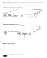
Management Options Chapter 1 Product Overview RPS Connector on the Catalyst 3524-PWR XL Switch The Cisco RPS 300 (model PWR300-AC-RPS) has two output levels: -48V and 12V with a total output power of 300W. It provides a fully-redundant power source for up to six switches. It automatically senses when one of the switches has experienced power failure and automatically sends power to the affected switch. Although it supports up to six switches, it can power only one switch at a time. If more than one switch fails at the same time, the subsequent switches will not be powered. Warning Attach only the Cisco RPS (model PWR300-AC-RPS) to the RPS receptacle. For more information on the Cisco RPS 300, refer to the Cisco Redundant Power System 300 Hardware Installation Guide. Console Port You can connect a Catalyst 3500 XL switch to a PC by means of the console port and the supplied rollover cable and DB-9 adapter. You need to provide a RJ-45-to-DB-25 female DTE adapter if you want to connect the switch console port to a terminal. You can order a kit (part number ACS-DSBUASYN=) containing that adapter from Cisco. For console port and adapter pinout information, see the "Cable and Adapter Specifications" section on page B-4. Management Options Catalyst 3500 XL switches offer several management options: • Cisco Cluster Management Suite This suite is made up of four web-based applications that you use to create, monitor, and configure a cluster of switches or an individual switch. You use the Cluster Builder, Cluster View, and Cluster Manager applications to create, configure, and monitor clusters. You use the Visual Switch Manager (VSM) application to manage individual and standalone switches. For more information, refer to the Cisco IOS Desktop Switching Software Configuration Guide and the online help for these applications. 1-24 Catalyst 3500 Series XL Hardware Installation Guide 78-6456-04
-
 1
1 -
2
-
3
-
4
-
5
-
6
-
7
-
8
-
9
-
10
-
11
-
12
-
13
-
14
-
15
-
16
-
17
-
18
-
19
-
20
-
21
-
22
-
23
-
24
-
25
-
26
-
27
-
28
-
29
-
30
-
31
-
32
-
33
-
34
-
35
-
36
-
37
-
38
-
39
-
40
-
41
-
42
-
 43
43 -
 44
44 -
 45
45 -
 46
46 -
 47
47 -
 48
48 -
 49
49 -
 50
50 -
 51
51 -
 52
52 -
 53
53 -
54
-
55
-
56
-
57
-
58
-
59
-
60
-
61
-
62
-
63
-
64
-
65
-
66
-
67
-
68
-
69
-
70
-
71
-
72
-
73
-
74
-
75
-
76
-
77
-
78
-
79
-
80
-
81
-
82
-
83
-
84
-
85
-
86
-
87
-
88
-
89
-
90
-
91
-
92
-
93
-
94
-
95
-
96
-
97
-
98
-
99
-
100
-
101
-
102
-
103
-
104
-
105
-
106
-
107
-
108
-
109
-
110
-
111
-
112
-
113
-
114
-
115
-
116
-
117
-
118
-
119
-
120
-
121
-
122
-
123
-
124
-
125
-
126
-
127
-
128
-
129
-
130
-
131
-
132
-
133
-
134
-
135
-
136
-
137
-
138
-
139
-
140
-
141
-
142
-
143
-
144
-
145
-
146
-
147
-
148
-
149
-
150
-
151
-
152
-
153
-
154
-
155
-
156
-
157
-
158
-
159
-
160
 |
 |