Cisco WS-C3560-8PC-S Installation Guide - Page 68
Removing Screws from the Switch
 |
UPC - 882658120404
View all Cisco WS-C3560-8PC-S manuals
Add to My Manuals
Save this manual to your list of manuals |
Page 68 highlights
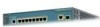
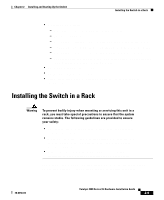
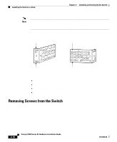
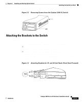
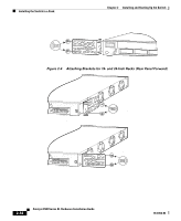
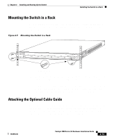
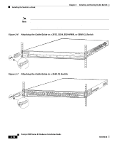
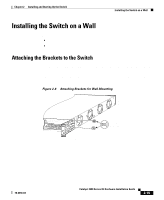
Installing the Switch in a Rack Chapter 2 Installing and Starting Up the Switch Note The illustrations in this section show the Catalyst 3508G XL switch as an example. Other switches in the series (Catalyst 3512, 3524, 3524-PWR, and 3548 XL) can also be installed as shown here. Figure 2-1 Bracket Mounting Points 19" rack mount point 24" rack mount point 38398 19" rack mount point 24" rack mount point To install the switch in a 19-inch or a 24-inch standard rack, follow the instructions described in these procedures: • Removing screws from the switch • Attaching the brackets to the switch • Mounting the switch in a rack • Attaching the optional cable guide Removing Screws from the Switch If you plan to install the Catalyst 3548 XL switch in a rack, you must first remove the front side screws in the switch chassis so that the mounting brackets can be attached. Figure 2-2 shows how to remove the chassis screw from one side of the switch. Follow the same procedure for the opposite side. 2-10 Catalyst 3500 Series XL Hardware Installation Guide 78-6456-04
-
 1
1 -
2
-
3
-
4
-
5
-
6
-
7
-
8
-
9
-
10
-
11
-
12
-
13
-
14
-
15
-
16
-
17
-
18
-
19
-
20
-
21
-
22
-
23
-
24
-
25
-
26
-
27
-
28
-
29
-
30
-
31
-
32
-
33
-
34
-
35
-
36
-
37
-
38
-
39
-
40
-
41
-
42
-
43
-
44
-
45
-
46
-
47
-
48
-
49
-
50
-
51
-
52
-
53
-
54
-
55
-
56
-
57
-
58
-
59
-
60
-
61
-
62
-
 63
63 -
 64
64 -
 65
65 -
 66
66 -
 67
67 -
 68
68 -
 69
69 -
 70
70 -
 71
71 -
 72
72 -
 73
73 -
74
-
75
-
76
-
77
-
78
-
79
-
80
-
81
-
82
-
83
-
84
-
85
-
86
-
87
-
88
-
89
-
90
-
91
-
92
-
93
-
94
-
95
-
96
-
97
-
98
-
99
-
100
-
101
-
102
-
103
-
104
-
105
-
106
-
107
-
108
-
109
-
110
-
111
-
112
-
113
-
114
-
115
-
116
-
117
-
118
-
119
-
120
-
121
-
122
-
123
-
124
-
125
-
126
-
127
-
128
-
129
-
130
-
131
-
132
-
133
-
134
-
135
-
136
-
137
-
138
-
139
-
140
-
141
-
142
-
143
-
144
-
145
-
146
-
147
-
148
-
149
-
150
-
151
-
152
-
153
-
154
-
155
-
156
-
157
-
158
-
159
-
160
 |
 |