Cisco WS-C3560-8PC-S Installation Guide - Page 74
Attaching the Switch to a Wall
 |
UPC - 882658120404
View all Cisco WS-C3560-8PC-S manuals
Add to My Manuals
Save this manual to your list of manuals |
Page 74 highlights
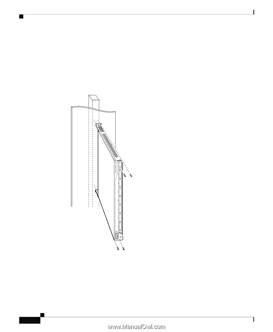
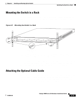
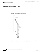
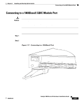
Installing the Switch on a Wall Chapter 2 Installing and Starting Up the Switch Attaching the Switch to a Wall For best support of the switch and cables, make sure the switch is attached securely to a wall stud or to a firmly attached plywood mounting backboard, as shown in Figure 2-9. Figure 2-9 Attaching the Switch to a Wall Vertical wall stud 8 User-supplied screws 7 6 5 4 3 2 Vertical wall-mount 1 STATUS UTIL DUPLEX SPEED SYSTEM RPS MODE 30061 After the switch is mounted on the wall, attach the power cord to the switch. If you are using the RPS, see the Cisco RPS documentation. After the power is connected, the system LED turns amber for 2 seconds, and then it flashes green while the switch completes a series of self-tests described in the "Powering On the Switch and Running POST" section on page 2-17. 2-16 Catalyst 3500 Series XL Hardware Installation Guide 78-6456-04
-
 1
1 -
2
-
3
-
4
-
5
-
6
-
7
-
8
-
9
-
10
-
11
-
12
-
13
-
14
-
15
-
16
-
17
-
18
-
19
-
20
-
21
-
22
-
23
-
24
-
25
-
26
-
27
-
28
-
29
-
30
-
31
-
32
-
33
-
34
-
35
-
36
-
37
-
38
-
39
-
40
-
41
-
42
-
43
-
44
-
45
-
46
-
47
-
48
-
49
-
50
-
51
-
52
-
53
-
54
-
55
-
56
-
57
-
58
-
59
-
60
-
61
-
62
-
63
-
64
-
65
-
66
-
67
-
68
-
 69
69 -
 70
70 -
 71
71 -
 72
72 -
 73
73 -
 74
74 -
 75
75 -
 76
76 -
 77
77 -
 78
78 -
 79
79 -
80
-
81
-
82
-
83
-
84
-
85
-
86
-
87
-
88
-
89
-
90
-
91
-
92
-
93
-
94
-
95
-
96
-
97
-
98
-
99
-
100
-
101
-
102
-
103
-
104
-
105
-
106
-
107
-
108
-
109
-
110
-
111
-
112
-
113
-
114
-
115
-
116
-
117
-
118
-
119
-
120
-
121
-
122
-
123
-
124
-
125
-
126
-
127
-
128
-
129
-
130
-
131
-
132
-
133
-
134
-
135
-
136
-
137
-
138
-
139
-
140
-
141
-
142
-
143
-
144
-
145
-
146
-
147
-
148
-
149
-
150
-
151
-
152
-
153
-
154
-
155
-
156
-
157
-
158
-
159
-
160
 |
 |