Cisco WS-C3560-8PC-S Installation Guide - Page 75
Installing the Switch on a Table or Shelf, Powering On the Switch and Running POST
 |
UPC - 882658120404
View all Cisco WS-C3560-8PC-S manuals
Add to My Manuals
Save this manual to your list of manuals |
Page 75 highlights
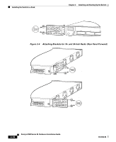
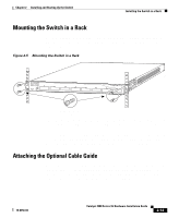
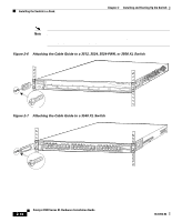
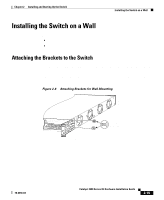
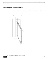
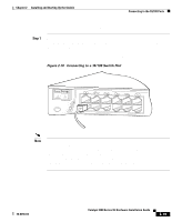
Chapter 2 Installing and Starting Up the Switch Installing the Switch on a Table or Shelf Installing the Switch on a Table or Shelf Follow these steps to install the switch on a table or shelf: Step 1 Step 2 Step 3 Locate the adhesive strip with the rubber feet in the mounting-kit envelope. Attach the four rubber feet to the recessed areas on the bottom of the unit. Place the switch on the table or shelf near an AC power source. Connect the power cord to the switch rear panel and to the power outlet. If you are using the RPS, see the RPS documentation for installation instructions. After the power is connected, the system LED turns amber for 2 seconds, and then it flashes green while the switch completes POST. Powering On the Switch and Running POST If your configuration has an RPS, see the "Power Connectors" section on page 1-22 and the Cisco RPS documentation. To power on the switch after you install it, follow these steps: Step 1 Step 2 Step 3 Make sure that you have started the emulation software program (such as ProComm, HyperTerminal, tip, or minicom) from your management station. Connect one end of the AC power cord to the AC power connector on the switch. Connect the other end of the power cord to an AC power outlet. As the switch powers on, it begins POST, a series of eight tests that run automatically to ensure that the switch functions properly. When the switch begins POST, the port LEDs turn amber for 2 seconds, and then they turn green. The System LED flashes green, and the RPS LED turns off. As each test runs, the port LEDs, starting with number 1, turn off. The port LEDs for ports 2 to 8 each turn off in turn as the system completes a test. 78-6456-04 Catalyst 3500 Series XL Hardware Installation Guide 2-17
-
 1
1 -
2
-
3
-
4
-
5
-
6
-
7
-
8
-
9
-
10
-
11
-
12
-
13
-
14
-
15
-
16
-
17
-
18
-
19
-
20
-
21
-
22
-
23
-
24
-
25
-
26
-
27
-
28
-
29
-
30
-
31
-
32
-
33
-
34
-
35
-
36
-
37
-
38
-
39
-
40
-
41
-
42
-
43
-
44
-
45
-
46
-
47
-
48
-
49
-
50
-
51
-
52
-
53
-
54
-
55
-
56
-
57
-
58
-
59
-
60
-
61
-
62
-
63
-
64
-
65
-
66
-
67
-
68
-
69
-
 70
70 -
 71
71 -
 72
72 -
 73
73 -
 74
74 -
 75
75 -
 76
76 -
 77
77 -
 78
78 -
 79
79 -
 80
80 -
81
-
82
-
83
-
84
-
85
-
86
-
87
-
88
-
89
-
90
-
91
-
92
-
93
-
94
-
95
-
96
-
97
-
98
-
99
-
100
-
101
-
102
-
103
-
104
-
105
-
106
-
107
-
108
-
109
-
110
-
111
-
112
-
113
-
114
-
115
-
116
-
117
-
118
-
119
-
120
-
121
-
122
-
123
-
124
-
125
-
126
-
127
-
128
-
129
-
130
-
131
-
132
-
133
-
134
-
135
-
136
-
137
-
138
-
139
-
140
-
141
-
142
-
143
-
144
-
145
-
146
-
147
-
148
-
149
-
150
-
151
-
152
-
153
-
154
-
155
-
156
-
157
-
158
-
159
-
160
 |
 |