Cisco WS-C3560-8PC-S Installation Guide - Page 78
Connecting to the GBIC Module Ports
 |
UPC - 882658120404
View all Cisco WS-C3560-8PC-S manuals
Add to My Manuals
Save this manual to your list of manuals |
Page 78 highlights
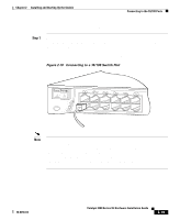
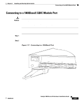
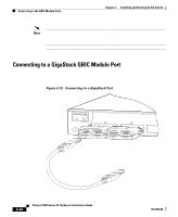
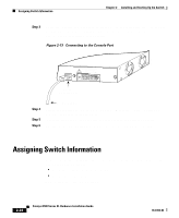
Connecting to the GBIC Module Ports Chapter 2 Installing and Starting Up the Switch Step 2 Step 3 Step 4 Connect the other end of the cable to an RJ-45 connector of the other device. The port LED comes on when both the switch and the connected device have established link. The port LED is amber while Spanning Tree Protocol (STP) discovers the topology and searches for loops. This takes about 30 seconds, and then the port LED turns green. If the port LED does not come on, the device at the other end might not be turned on, or there might be a cable problem or a problem with the adapter installed in the attached device. See Chapter 3, "Troubleshooting," for solutions to cabling problems. Reconfigure and reboot the connected device if necessary. Repeat steps 1 through 3 to connect each device. Connecting to the GBIC Module Ports Note Install the Gigabit Interface Converters (GBICs) as described in the "GBIC Module Slots" section on page 1-9, and then connect to the 1000BaseX ports. For detailed instructions on installing, removing, and cabling the GBICs (1000BaseSX module or the 1000BaseLX/LH module), refer to the GBIC documentation. For detailed instructions on installing and cabling the GigaStack GBICs, see the Catalyst GigaStack Gigabit Interface Converter Hardware Installation Guide. 2-20 Catalyst 3500 Series XL Hardware Installation Guide 78-6456-04
-
 1
1 -
2
-
3
-
4
-
5
-
6
-
7
-
8
-
9
-
10
-
11
-
12
-
13
-
14
-
15
-
16
-
17
-
18
-
19
-
20
-
21
-
22
-
23
-
24
-
25
-
26
-
27
-
28
-
29
-
30
-
31
-
32
-
33
-
34
-
35
-
36
-
37
-
38
-
39
-
40
-
41
-
42
-
43
-
44
-
45
-
46
-
47
-
48
-
49
-
50
-
51
-
52
-
53
-
54
-
55
-
56
-
57
-
58
-
59
-
60
-
61
-
62
-
63
-
64
-
65
-
66
-
67
-
68
-
69
-
70
-
71
-
72
-
 73
73 -
 74
74 -
 75
75 -
 76
76 -
 77
77 -
 78
78 -
 79
79 -
 80
80 -
 81
81 -
 82
82 -
 83
83 -
84
-
85
-
86
-
87
-
88
-
89
-
90
-
91
-
92
-
93
-
94
-
95
-
96
-
97
-
98
-
99
-
100
-
101
-
102
-
103
-
104
-
105
-
106
-
107
-
108
-
109
-
110
-
111
-
112
-
113
-
114
-
115
-
116
-
117
-
118
-
119
-
120
-
121
-
122
-
123
-
124
-
125
-
126
-
127
-
128
-
129
-
130
-
131
-
132
-
133
-
134
-
135
-
136
-
137
-
138
-
139
-
140
-
141
-
142
-
143
-
144
-
145
-
146
-
147
-
148
-
149
-
150
-
151
-
152
-
153
-
154
-
155
-
156
-
157
-
158
-
159
-
160
 |
 |