Cisco WS-C3560-8PC-S Installation Guide - Page 92
Understanding POST Results
 |
UPC - 882658120404
View all Cisco WS-C3560-8PC-S manuals
Add to My Manuals
Save this manual to your list of manuals |
Page 92 highlights
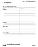
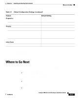
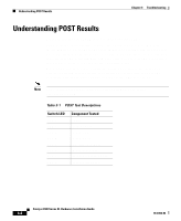
Understanding POST Results Chapter 3 Troubleshooting Understanding POST Results Table 3-1 lists the eight POST tests and their associated LEDs. POST tests run automatically each time the switch is powered on. When the switch begins POST, the port LEDs turn amber for 2 seconds, and then they turn green. The System LED flashes green, and the RPS LED turns off. As each test runs, the port LEDs, starting with number 1, turn off. The port LEDs for ports 2 to 8 each turn off in turn as the system completes a test. When POST completes successfully, the port LEDs return to the status mode display, indicating that the switch is operational. If a test fails, the port LED associated with the test turns amber, and the system LED turns amber. Note POST failures are usually fatal. Call Cisco Systems if your switch does not pass POST. Table 3-1 POST Test Descriptions Switch LED LED 1 LED 2 LED 3 LED 4 LED 5 LED 6 LED 7 LED 8 Component Tested DRAM Flash memory Switch CPU System board CPU interface ASIC Switch core ASIC Ethernet controller ASIC Ethernet interfaces Catalyst 3500 Series XL Hardware Installation Guide 3-2 78-6456-04
-
 1
1 -
2
-
3
-
4
-
5
-
6
-
7
-
8
-
9
-
10
-
11
-
12
-
13
-
14
-
15
-
16
-
17
-
18
-
19
-
20
-
21
-
22
-
23
-
24
-
25
-
26
-
27
-
28
-
29
-
30
-
31
-
32
-
33
-
34
-
35
-
36
-
37
-
38
-
39
-
40
-
41
-
42
-
43
-
44
-
45
-
46
-
47
-
48
-
49
-
50
-
51
-
52
-
53
-
54
-
55
-
56
-
57
-
58
-
59
-
60
-
61
-
62
-
63
-
64
-
65
-
66
-
67
-
68
-
69
-
70
-
71
-
72
-
73
-
74
-
75
-
76
-
77
-
78
-
79
-
80
-
81
-
82
-
83
-
84
-
85
-
86
-
 87
87 -
 88
88 -
 89
89 -
 90
90 -
 91
91 -
 92
92 -
 93
93 -
 94
94 -
 95
95 -
 96
96 -
 97
97 -
98
-
99
-
100
-
101
-
102
-
103
-
104
-
105
-
106
-
107
-
108
-
109
-
110
-
111
-
112
-
113
-
114
-
115
-
116
-
117
-
118
-
119
-
120
-
121
-
122
-
123
-
124
-
125
-
126
-
127
-
128
-
129
-
130
-
131
-
132
-
133
-
134
-
135
-
136
-
137
-
138
-
139
-
140
-
141
-
142
-
143
-
144
-
145
-
146
-
147
-
148
-
149
-
150
-
151
-
152
-
153
-
154
-
155
-
156
-
157
-
158
-
159
-
160
 |
 |