Cisco WS-C3560G-48TS-E Installation Guide
Cisco WS-C3560G-48TS-E - Catalyst 3560G-48TS - Switch Manual
 |
UPC - 746320942575
View all Cisco WS-C3560G-48TS-E manuals
Add to My Manuals
Save this manual to your list of manuals |
Cisco WS-C3560G-48TS-E manual content summary:
- Cisco WS-C3560G-48TS-E | Installation Guide - Page 1
Catalyst 3500 Series XL Hardware Installation Guide August 2003 Corporate Headquarters Cisco Systems, Inc. 170 West Tasman Drive San Jose, CA 95134-1706 USA http://www.cisco.com Tel: 408 526-4000 800 553-NETS (6387) Fax: 408 526-4100 Customer Order Number: DOC-786456= Text Part Number: 78-6456-04 - Cisco WS-C3560G-48TS-E | Installation Guide - Page 2
in accordance with the instruction manual, may cause harmful Cisco's installation instructions, it may cause interference with radio and television reception. This equipment has been tested and found to comply with the limits for a Class B digital device in accordance with the specifications - Cisco WS-C3560G-48TS-E | Installation Guide - Page 3
, and iQuick Study are service marks of Cisco Systems, Inc.; and Aironet, ASIST, BPX, Catalyst, CCDA, CCDP, CCIE, CCNA, CCNP, Cisco, the Cisco Certified Internetwork Expert logo, Cisco IOS, the Cisco IOS logo, Cisco Press, Cisco Systems, Cisco Systems Capital, the Cisco Systems logo, Empowering the - Cisco WS-C3560G-48TS-E | Installation Guide - Page 4
- Cisco WS-C3560G-48TS-E | Installation Guide - Page 5
Cisco TAC Website xx Opening a TAC Case xxi TAC Case Priority Definitions xxi Obtaining Additional Publications and Information xxii Product Overview 1-1 Features 1-1 Front-Panel Description 1-5 10/100 Ports 1-7 GBIC Module Slots 1-9 78-6456-03 Catalyst 3500 Series XL Hardware Installation Guide - Cisco WS-C3560G-48TS-E | Installation Guide - Page 6
Panel Description 1-21 Power Connectors 1-22 Internal Power Supply Connector 1-23 Cisco RPS Connector 1-23 Console Port 1-24 Management Options 1-24 Network 2-7 Installation Guidelines 2-7 Verifying Package Contents 2-8 Catalyst 3500 Series XL Hardware Installation Guide vi 78-6456-03 - Cisco WS-C3560G-48TS-E | Installation Guide - Page 7
Attaching the Brackets to the Switch 2-11 Mounting the Switch in a Rack 2-13 Attaching the Optional Cable Guide 2-13 Installing the Switch on a Wall Troubleshooting 3-1 Understanding POST Results 3-2 Diagnosing Problems 3-3 Contents 78-6456-03 Catalyst 3500 Series XL Hardware Installation Guide - Cisco WS-C3560G-48TS-E | Installation Guide - Page 8
to a Terminal B-7 Translated Safety Warnings C-1 Attaching the Cisco RPS (model PWR600-AC-RPS) C-2 Attaching the Cisco RPS (model PWR300-AC-RPS-N1) C-4 Service Personnel Warning C-5 Qualified Personnel Warning C-7 Installation Instructions Warning C-9 Jewelry Removal Warning C-10 Stacking the - Cisco WS-C3560G-48TS-E | Installation Guide - Page 9
Warning C-27 Work During Lightning Activity Warning C-30 Product Disposal Warning C-31 Chassis Warning-Rack-Mounting and Servicing C-33 Chassis Power Connection Warning C-38 Shock Hazard from Interconnections Warning C-41 Contents 78-6456-03 Catalyst 3500 Series XL Hardware Installation Guide ix - Cisco WS-C3560G-48TS-E | Installation Guide - Page 10
Contents Catalyst 3500 Series XL Hardware Installation Guide x 78-6456-03 - Cisco WS-C3560G-48TS-E | Installation Guide - Page 11
Hardware Installation Guide documents the hardware features of Catalyst 3500 series XL switches. It describes the physical and performance characteristics of the switches in the series, explains how to install a switch and set up its initial configuration, provides troubleshooting information, and - Cisco WS-C3560G-48TS-E | Installation Guide - Page 12
a switch on a rack, wall, table, or shelf. It also describes how to set up the switch initial configuration. Chapter 3, "Troubleshooting," describes how to identify and resolve some of the problems that might arise when you are installing the switch. Appendix A, "Technical Specifications," lists the - Cisco WS-C3560G-48TS-E | Installation Guide - Page 13
or references to materials not contained in this manual. Caution Means reader be careful. In this situation in equipment damage or loss of data. Warning IMPORTANT SAFETY INSTRUCTIONS This warning symbol means danger. You are in a situation Catalyst 3500 Series XL Hardware Installation Guide xiii - Cisco WS-C3560G-48TS-E | Installation Guide - Page 14
traduites qui accompagnent cet appareil, référez-vous au numéro de l'instruction situé à la fin de chaque avertissement. CONSERVEZ CES INFORMATIONS Warnung WICHTIGE Gerät ausgeliefert wurden. BEWAHREN SIE DIESE HINWEISE GUT AUF. Catalyst 3500 Series XL Hardware Installation Guide xiv 78-6456-04 - Cisco WS-C3560G-48TS-E | Installation Guide - Page 15
ao final de cada aviso para localizar sua tradução nos avisos de segurança traduzidos que acompanham este dispositivo. GUARDE ESTAS INSTRUÇÕES 78-6456-04 Catalyst 3500 Series XL Hardware Installation Guide xv - Cisco WS-C3560G-48TS-E | Installation Guide - Page 16
änd det nummer som finns i slutet av varje varning för att hitta dess översättning i de översatta säkerhetsvarningar som medföljer denna anordning. SPARA DESSA ANVISNINGAR Catalyst 3500 Series XL Hardware Installation Guide xvi 78-6456-04 - Cisco WS-C3560G-48TS-E | Installation Guide - Page 17
Preface Conventions 78-6456-04 Catalyst 3500 Series XL Hardware Installation Guide xvii - Cisco WS-C3560G-48TS-E | Installation Guide - Page 18
to the following publications: • Quick Start: Catalyst 3500 Series XL Cabling and Setup • Cisco IOS Desktop Switching Software Configuration Guide • Cisco IOS Desktop Switching Command Reference (online only) • Cisco Cluster Management Suite online help provides detailed procedures for using a Web - Cisco WS-C3560G-48TS-E | Installation Guide - Page 19
Cisco.com users can order documentation through a local account representative by calling Cisco Systems Corporate Headquarters (California, USA.) at 408 526-7208 or, elsewhere in North America, by calling 800 553-NETS (6387). 78-6456-04 Catalyst 3500 Series XL Hardware Installation Guide - Cisco WS-C3560G-48TS-E | Installation Guide - Page 20
award-winning technical support services, online and over the phone. Cisco.com features the Cisco TAC website as an online starting point for technical assistance. Cisco TAC Website The Cisco TAC website (http://www.cisco.com/tac) provides online documents and tools for troubleshooting and resolving - Cisco WS-C3560G-48TS-E | Installation Guide - Page 21
Obtaining Technical Assistance Opening a TAC Case The online TAC Case Open Tool (http://www.cisco.com/tac/caseopen) is the fastest way Cisco will commit resources during normal business hours to restore service to satisfactory levels. 78-6456-04 Catalyst 3500 Series XL Hardware Installation Guide - Cisco WS-C3560G-48TS-E | Installation Guide - Page 22
: Internetworking Terms and Acronyms Dictionary, Internetworking Technology Handbook, Internetworking Troubleshooting Guide, and the Internetworking Design Guide. For current Cisco Press titles and other information, go to Cisco Press online at this URL: http://www.ciscopress.com • Packet magazine - Cisco WS-C3560G-48TS-E | Installation Guide - Page 23
/ac123/ac147/about_cisco_the_internet_ protocol_journal.html • Training-Cisco offers world-class networking training. Current offerings in network training are listed at this URL: http://www.cisco.com/en/US/learning/index.html 78-6456-04 Catalyst 3500 Series XL Hardware Installation Guide xxiii - Cisco WS-C3560G-48TS-E | Installation Guide - Page 24
Obtaining Additional Publications and Information Preface xxiv Catalyst 3500 Series XL Hardware Installation Guide 78-6456-04 - Cisco WS-C3560G-48TS-E | Installation Guide - Page 25
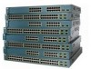
10/100 and Gigabit Ethernet traffic from other network devices. A feature specific to the Catalyst 3524-PWR XL switch is its ability to provide inline power to Cisco IP Phones. (Phone adapters are not required when connecting to the Catalyst 3524-PWR XL 10/100 switch ports.) Figure 1-1 shows the - Cisco WS-C3560G-48TS-E | Installation Guide - Page 26
Features Chapter 1 Product Overview Figure 1-1 Catalyst 3500 Series XL Switches Switch Description WS-C3508G-XL 8 GBIC1-based gigabit module slots 1 SYSTEM 2 3 RPS 4 5 MODE STATUS UTIL DUPLX SPEED 6 7 8 WS 30210 Catalyst 3500 Series XL Hardware Installation Guide 1-2 78-6456-04 - Cisco WS-C3560G-48TS-E | Installation Guide - Page 27
- GigaStack GBIC module - 1000BaseSX GBIC module - 1000BaseLX/LH GBIC module - 1000BaseZX GBIC module (support for up to four 1000BaseZX GBICs with the Catalyst 3508G XL switch) Management • Cisco IOS command-line interface (CLI) through the console port or Telnet • CiscoView device-management - Cisco WS-C3560G-48TS-E | Installation Guide - Page 28
from broadcast storms • SPAN port monitoring on any port • Support for command switch redundancy • Support for Cisco GBIC modules - GigaStack GBIC - 1000BaseSX GBIC module - 1000BaseLX/LH GBIC module - 1000BaseZX GBIC module Catalyst 3500 Series XL Hardware Installation Guide 1-4 78-6456-04 - Cisco WS-C3560G-48TS-E | Installation Guide - Page 29
Chapter 1 Product Overview Front-Panel Description Table 1-2 Catalyst 3512, 3524, 3524-PWR, and 3548 XL Features (continued) Feature Description (continued) Management • Cisco IOS CLI through the console port or Telnet • CiscoView device-management application • Cluster Management Suite, a - Cisco WS-C3560G-48TS-E | Installation Guide - Page 30
RPS 2X STATUS UTIL DUPLX SPEED 9 10 11 12 11X 12X 10/100 ports Figure 1-4 Catalyst 3524 XL Switch 1 2 GBIC module slots 12 1X 34 56 78 MODE SYSTEM RPS STATUS 2X 10/100 ports 1 2 GBIC module slots Catalyst 3500 Series XL Hardware Installation Guide 1-6 26237 26235 78-6456-04 - Cisco WS-C3560G-48TS-E | Installation Guide - Page 31
ports can connect, up to a distance of 100 meters, to any compatible network device: • 10BaseT-compatible devices such as workstations, Cisco IP Phones, and hubs through standard RJ-45 connectors and Category 3, 4, or 5 cabling 78-6456-04 Catalyst 3500 Series XL Hardware Installation Guide 1-7 - Cisco WS-C3560G-48TS-E | Installation Guide - Page 32
and 3548 XL switches provide protocol support for Cisco IP Phones. The Catalyst 3548 and 3524-PWR XL switches also support per-port priority override. Refer to the Cisco IOS Desktop Switching Software Configuration Guide for more information about these features. Cisco IP Phones-connected to the 10 - Cisco WS-C3560G-48TS-E | Installation Guide - Page 33
power even if a Cisco IP Phone is connected to it. You also can connect the Cisco IP Phone to a Catalyst 3524-PWR XL 10/100 Gbps stack configuration of up to nine Catalyst 3500 XL switches. The GigaStack GBIC supports one full-duplex link (in a Catalyst 3500 Series XL Hardware Installation Guide 1-9 - Cisco WS-C3560G-48TS-E | Installation Guide - Page 34
Figure 1-8 Installing a GigaStack GBIC Module in the Switch Metal flap door 22081 1 SYSTEM RPS MODE STATUS UTIL DUPLX SPEED 2 3 1 2 GigaStack GBIC GBIC module slot 1-10 Catalyst 3500 Series XL Hardware Installation Guide 78-6456-04 - Cisco WS-C3560G-48TS-E | Installation Guide - Page 35
in this section except the utilization meter (UTL) are visible on the VSM home page and Cluster Manager page. The Cisco IOS Desktop Switching Software Configuration Guide describes how to use the Cluster Management Suite to monitor individual switches and how to use cluster management software to - Cisco WS-C3560G-48TS-E | Installation Guide - Page 36
Figure 1-10 Catalyst 3512 and 3524 XL LEDs Port LEDs Chapter 1 Product Overview SYSTEM RPS MODE STATUS UTIL DUPLX SPEED Mode button 1 1X 23 45 67 8 9 10 11 12 11X 2X 12X System LED Redundant power system LED 22028 1-12 Catalyst 3500 Series XL Hardware Installation Guide 78-6456 - Cisco WS-C3560G-48TS-E | Installation Guide - Page 37
Chapter 1 Product Overview Figure 1-11 Catalyst 3524-PWR XL LEDs Port LEDs Front-Panel Description 30292 MODE SYSTEM RPS STATUS DUPLX SPEED LINE LED Redundant power system LED Status LED Duplex LED Speed LED Line power LED 78-6456-04 Catalyst 3500 Series XL Hardware Installation Guide 1-13 - Cisco WS-C3560G-48TS-E | Installation Guide - Page 38
Front-Panel Description Figure 1-12 Catalyst 3548 XL LEDs Port LEDs Chapter 1 Product Overview SYSTEM RPS STATUS UTIL DUPLX SPEED MODE 1 1X 23 POST, see the "Powering On the Switch and Running POST" section on page 2-17. 1-14 Catalyst 3500 Series XL Hardware Installation Guide 78-6456-04 - Cisco WS-C3560G-48TS-E | Installation Guide - Page 39
. The LEDs display correctly for RPS revision level Z3 or later. The label on the bottom of the RPS shows the revision level. Note The Cisco RPS 300 (model PWR300-AC-RPS) supports the Catalyst 3524-PWR XL switch. 78-6456-04 Catalyst 3500 Series XL Hardware Installation Guide 1-15 - Cisco WS-C3560G-48TS-E | Installation Guide - Page 40
information about the failure conditions on the Cisco RPS 300, refer to the Cisco Redundant Power System 300 Hardware Installation Guide. Port LEDs and Modes Each 10/ change the port mode. Note To change the port mode in the Catalyst 3548 XL switch, press the Mode label. Table 1-6 Port Mode LEDs - Cisco WS-C3560G-48TS-E | Installation Guide - Page 41
inline power status: on or off. Table 1-7 Meaning of LED Colors in Different Modes on the Catalyst 3508, 3512, 3524, and 3548 XL Switches Port Mode STATUS (port status) UTL (utilization) . Port is operating in full duplex. 78-6456-04 Catalyst 3500 Series XL Hardware Installation Guide 1-17 - Cisco WS-C3560G-48TS-E | Installation Guide - Page 42
is operating at 1000 Mbps. Table 1-8 Meaning of LED Colors in Different Modes on the Catalyst 3524-PWR XL Switch Port Mode STATUS (port status) DUPLEX LED Color Off Solid green Flashing . Port is operating in full duplex. 1-18 Catalyst 3500 Series XL Hardware Installation Guide 78-6456-04 - Cisco WS-C3560G-48TS-E | Installation Guide - Page 43
in Different Modes on the Catalyst 3524-PWR XL Switch Port Cisco IP Phone is receiving power from an AC power source, the port LED is off even if the IP phone Bandwidth Utilization for the Catalyst 3508G XL Switch 1 MODE SYSTEM RPS STATUS UTIL DUPLX SPEED 2 3 4 5 Catalyst 3500 XL 6 7 - Cisco WS-C3560G-48TS-E | Installation Guide - Page 44
23 24 15X 14X 16X < 25% + 25% - 49% + 50% + Catalyst 3500 XL 1 2 Figure 1-16 Bandwidth Utilization for the Catalyst 3548 XL Switch 28366 SYSTEM RPS STATUS UTIL DUPLX SPEED MODE 12 1X 3 24 total capacity, and so on. 1-20 Catalyst 3500 Series XL Hardware Installation Guide 78-6456-04 - Cisco WS-C3560G-48TS-E | Installation Guide - Page 45
1-18, and Figure 1-20), which are described in this section. Figure 1-17 Catalyst 3508G XL Rear Panel 18963 RATING 100-127/200-240V~ 1.5A/0.75A 50-60HZ MANUAL. +5V @24A, +12V @.5A RJ-45 console port Redundant power system connector Fans Catalyst 3500 Series XL Hardware Installation Guide 1-21 - Cisco WS-C3560G-48TS-E | Installation Guide - Page 46
SUPPLY SPECIFIED IN MANUAL +3.3V @17A, +12 @1.1A CONSOLE AC power connector Fan exhaust RJ-45 console port Redundant power system connector Power Connectors You can provide power to the switch either through the internal power supply or through the Cisco RPS. 1-22 Catalyst 3500 Series XL - Cisco WS-C3560G-48TS-E | Installation Guide - Page 47
to an AC power outlet. Cisco RPS Connector Specific Cisco RPS models support specific Catalyst 3500 XL switches: • Cisco RPS 600 (model PWR600-AC-RPS)-Supports the Catalyst 3512, 3524, 3548, and 3508 XL switches • Cisco RPS 300 (model PWR300-AC-RPS)-Supports the Catalyst 3524-PWR XL switch RPS - Cisco WS-C3560G-48TS-E | Installation Guide - Page 48
clusters. You use the Visual Switch Manager (VSM) application to manage individual and standalone switches. For more information, refer to the Cisco IOS Desktop Switching Software Configuration Guide and the online help for these applications. 1-24 Catalyst 3500 Series XL Hardware Installation - Cisco WS-C3560G-48TS-E | Installation Guide - Page 49
the switch from a remote location. See the Cisco IOS Desktop Switching Command Reference for more information. • platforms such as HP OpenView or SunNet Manager. The switch supports a comprehensive set of MIB extensions and MIB II, the Catalyst 3500 Series XL Hardware Installation Guide 1-25 - Cisco WS-C3560G-48TS-E | Installation Guide - Page 50
feature between the switch and its connected servers and routers. • An evolving demand for IP telephony • Use quality of service (QoS) to prioritize applications such as IP telephony during congestion and to help control both delay and jitter within the network. Use switches that support - Cisco WS-C3560G-48TS-E | Installation Guide - Page 51
to a gigabit backbone switch such as the Catalyst 3508G XL switch. If one of the redundant and the Catalyst 3508G XL switch as a switch cluster to manage them through a single IP address. • different VLANs and subnets, you can connect the Catalyst 3500 XL switches, again in a star configuration - Cisco WS-C3560G-48TS-E | Installation Guide - Page 52
cluster High-Performance Workgroup Catalyst 3508 XL or 4908G-L3 switch Catalyst 3500 XL cluster Redundant Gigabit Backbone Catalyst 4908G-L3 switch Catalyst 4908G-L3 switch 1 Gbps HSRP 33090 Catalyst 3500 XL cluster 1-28 Catalyst 3500 Series XL Hardware Installation Guide 78-6456-04 - Cisco WS-C3560G-48TS-E | Installation Guide - Page 53
network resources. It is required if numerous segments require access to the servers. The Catalyst 3500 XL switches in this network are connected through a GigaStack GBIC on each switch access to the Internet through one line. 78-6456-04 Catalyst 3500 Series XL Hardware Installation Guide 1-29 - Cisco WS-C3560G-48TS-E | Installation Guide - Page 54
Network Configuration Examples Chapter 1 Product Overview Figure 1-22 Small- to Medium-Sized Network Configuration Cisco 2600 router Catalyst 3500 XL GigaStack cluster 100 Mbps (200 Mbps full duplex) Gigabit server 1 Gbps (2 Gbps full duplex) Gigabit server 10/100 Mbps (20/200 Mbps full - Cisco WS-C3560G-48TS-E | Installation Guide - Page 55
, and control calls from their PCs. Using Cisco IP Phones, Cisco CallManager software, and Cisco SoftPhone software integrates telephony and IP networks, where the IP network supports both voice and data. Each 10/100 inline-power port on the Catalyst 3524-PWR XL switches provides -48V DC power - Cisco WS-C3560G-48TS-E | Installation Guide - Page 56
Fast EtherChannel (400 Mbps full duplex Fast EtherChannel) Catalyst 3524-PWR XL GigaStack cluster IP IP AC power source Workstations running Cisco SoftPhone software IP IP Cisco IP Phones IP IP IP Cisco IP Phones 33092 1-32 Catalyst 3500 Series XL Hardware Installation Guide 78-6456-04 - Cisco WS-C3560G-48TS-E | Installation Guide - Page 57
, and IP phone features and configuration. • Cisco Access gateway (such as Cisco Access Digital Trunk Gateway or Cisco Access Analog Trunk Gateway) that connects the IP network to the Public Switched Telephone Network (PSTN) or to users in an IP telephony network. 78-6456-04 Catalyst 3500 Series - Cisco WS-C3560G-48TS-E | Installation Guide - Page 58
2900 XL GigaStack cluster 1 Gbps (2 Gbps full duplex) Catalyst 3524-PWR XL GigaStack cluster IP IP AC Workstations running power Cisco SoftPhone software source IP IP Cisco IP Phones IP IP IP Cisco IP Phones 33093 1-34 Catalyst 3500 Series XL Hardware Installation Guide 78-6456-04 - Cisco WS-C3560G-48TS-E | Installation Guide - Page 59
and Starting Up the Switch This chapter describes how to install and start up your Catalyst 3500 XL switches and to interpret the power-on self-test (POST) that ensures • Default configuration settings • Where to go next 78-6456-04 Catalyst 3500 Series XL Hardware Installation Guide 2-1 - Cisco WS-C3560G-48TS-E | Installation Guide - Page 60
Service Personnel. Statement 88 Warning Only trained and qualified personnel should be allowed to install or replace this equipment. Statement 49 Warning Read the installation instructions main disconnecting device. Statement 66 Catalyst 3500 Series XL Hardware Installation Guide 2-2 78-6456-04 - Cisco WS-C3560G-48TS-E | Installation Guide - Page 61
. Statement 51 Warning Unplug the power cord before you work on a system that does not have an on/off switch. Statement 20 78-6456-04 Catalyst 3500 Series XL Hardware Installation Guide 2-3 - Cisco WS-C3560G-48TS-E | Installation Guide - Page 62
locate the circuit breaker on the panel board that services the DC circuit, switch the circuit breaker to Catalyst 3508, 3512, 3524, and 3548 XL switches: Warning Attach only the Cisco RPS (model PWR600-AC-RPS) to the RPS receptacle. Statement 100 Catalyst 3500 Series XL Hardware Installation Guide - Cisco WS-C3560G-48TS-E | Installation Guide - Page 63
warning applies to the Catalyst 3524-PWR XL switch: Warning Attach only the Cisco RPS (model PWR300-AC -RPS-N1) to the RPS receptacle. Statement 100B EMC Regulatory Statements U.S.A. Taiwan U.S. regulatory information for this product is in the front matter of this manual - Cisco WS-C3560G-48TS-E | Installation Guide - Page 64
is used in a domestic environment, radio disturbance may arise. When such trouble occurs, the user may be required to take corrective actions. Statement 191 mistake, it should be replaced with a residential-use type. Statement 294 Catalyst 3500 Series XL Hardware Installation Guide 2-6 78-6456-04 - Cisco WS-C3560G-48TS-E | Installation Guide - Page 65
from the switch to the connected devices are up to 10,000 meters. For specific cable lengths, refer to the documents that came with your GBICs. • For the from the switch to the connected devices are up to 1 meter. For specific cable lengths, refer to the document that came with the GigaStack GBIC. - Cisco WS-C3560G-48TS-E | Installation Guide - Page 66
or reseller for support. Return all packing materials to the shipping container, and save it. The switch is shipped with the following items: • Quick Start: Catalyst 3500 Series XL Cabling and Setup • This Catalyst 3500 Series XL Hardware Installation Guide • Cisco IOS Desktop Switching Software - Cisco WS-C3560G-48TS-E | Installation Guide - Page 67
the cable guide to one of the mounting brackets • One RJ-45-to-RJ-45 rollover cable • One RJ-45-to-DB-9 female adapter • Cisco Information Packet, containing warranty, safety, and support information Installing the Switch in a Rack Warning To prevent bodily injury when mounting or servicing this - Cisco WS-C3560G-48TS-E | Installation Guide - Page 68
24-inch standard rack, follow the instructions described in these procedures: • Removing screws from the switch • Attaching the brackets to the switch • Mounting the switch in a rack • Attaching the optional cable guide Removing Screws from the Switch If you plan to install the Catalyst 3548 XL - Cisco WS-C3560G-48TS-E | Installation Guide - Page 69
Rack Figure 2-2 Removing Screws from the Catalyst 3548 XL Switch 46 47 48 47X 1 2 48X Catalyst rack. Use two of the supplied screws to attach each bracket, according to the following guidelines: • For a 19-inch rack For a 24-inch rack, use the supplied number 24-Inch Racks (Front Panel Forward) Phillips - Cisco WS-C3560G-48TS-E | Installation Guide - Page 70
2 3 24" Configuration Figure 2-4 Attaching Brackets for 19- and 24-Inch Racks (Rear Panel Forward) 22439 22438 DC INPUTS SPECIFIED IFNOMRARNEUMAOL.T+E3P.3OVW***E@R1S4UAP, PLY head screws Phillips truss-head screws 22440 2-12 Catalyst 3500 Series XL Hardware Installation Guide 78-6456-04 - Cisco WS-C3560G-48TS-E | Installation Guide - Page 71
MODE STATUS 6 7 UTIL 8 DUPLX SPEED Phillips machine screws After the switch is mounted in the rack, attach the power cord to the switch. If you are using the Cisco RPS, see the Cisco RPS documentation for installation instructions. After the power is connected, the System LED turns amber for - Cisco WS-C3560G-48TS-E | Installation Guide - Page 72
22441 Installing the Switch in a Rack Chapter 2 Installing and Starting Up the Switch Note The Catalyst 3548 XL switch ships with a special cable guide as shown in Figure 2-7. This cable guide secures up to 48 cables. Use the supplied black screw to mount it on the left bracket. Figure 2-6 - Cisco WS-C3560G-48TS-E | Installation Guide - Page 73
bracket to the opposite side. Figure 2-8 Attaching Brackets for Wall-Mounting 30060 DC INPUTS SPECIFIED IFNOMRARNEUMAOL.T+E3P.3OVW***E@R1S4UAP, PLY DC INPUT +12V***@3A For vertical wall-mounting Phillips flat-head screws 78-6456-04 Catalyst 3500 Series XL Hardware Installation Guide 2-15 - Cisco WS-C3560G-48TS-E | Installation Guide - Page 74
2 Installing and Starting Up the Switch Attaching the Switch to a Wall For best support of the switch and cables, make sure the switch is attached securely to a wall stud or to a firmly attached plywood mounting backboard, as shown in Figure 2-9. Figure 2-9 Attaching the Switch to a Wall Vertical - Cisco WS-C3560G-48TS-E | Installation Guide - Page 75
strip with the rubber feet in the mounting-kit envelope. Attach the four rubber feet see the RPS documentation for installation instructions. After the power is connected, section on page 1-22 and the Cisco RPS documentation. To power on the Catalyst 3500 Series XL Hardware Installation Guide 2-17 - Cisco WS-C3560G-48TS-E | Installation Guide - Page 76
the Cisco IP Phone before link has been established, you must wait 10 seconds before connecting another network device (other than another Cisco IP Phone) to that switch port. Failure to do so can result in damage to that network device. 2-18 Catalyst 3500 Series XL Hardware Installation Guide 78 - Cisco WS-C3560G-48TS-E | Installation Guide - Page 77
might have more than one RJ-45 jack. Use the LAN-to-phone jack to connect the phone to the Catalyst 3524-PWR XL switch. Refer to the documentation that came with your Cisco IP Phone for information about connecting devices to it. 78-6456-04 Catalyst 3500 Series XL Hardware Installation Guide 2-19 - Cisco WS-C3560G-48TS-E | Installation Guide - Page 78
problem or a problem with the adapter installed in the attached device. See Chapter 3, "Troubleshooting," for solutions to cabling problems. instructions on installing and cabling the GigaStack GBICs, see the Catalyst GigaStack Gigabit Interface Converter Hardware Installation Guide. 2-20 Catalyst - Cisco WS-C3560G-48TS-E | Installation Guide - Page 79
fiber-optic receptacle, as shown in Figure 2-11. Figure 2-11 Connecting to a 1000BaseX Port 1 SYSTEM 2 RPS MODE STATUS UTIL DUPLX SPEED 22005 78-6456-04 Catalyst 3500 Series XL Hardware Installation Guide 2-21 - Cisco WS-C3560G-48TS-E | Installation Guide - Page 80
GBIC as shown in Figure 2-12. Figure 2-12 Connecting to a GigaStack Port 32708 MODE 1394 SYSTEM RPS STATUS UTIL DUPLX SPEED 1 1 2 1 2 2 GigaStack cable 1394 2-22 Catalyst 3500 Series XL Hardware Installation Guide 78-6456-04 - Cisco WS-C3560G-48TS-E | Installation Guide - Page 81
: • 9600 baud • 8 data bits • 1 stop bit • No parity After you have gained access to the switch, you can change the port baud rate. See the Cisco IOS Desktop Switching Software Configuration Guide for instructions. 78-6456-04 Catalyst 3500 Series XL Hardware Installation - Cisco WS-C3560G-48TS-E | Installation Guide - Page 82
FOR REMOTE POWER SUPPLY SPECIFIED IN MANUAL. +5V @24A, +12V @1. IP address information, host and cluster names, and passwords by two methods: • Using the setup program in the switch • Using a BOOTP server This section describes each method. 2-24 Catalyst 3500 Series XL Hardware Installation Guide - Cisco WS-C3560G-48TS-E | Installation Guide - Page 83
command switch, it is not necessary to assign IP information or a password. If you are configuring the switch as a standalone switch or as a command switch, you must assign IP information. Refer to the Cisco IOS Desktop Switching Software Configuration Guide for more information. You will need the - Cisco WS-C3560G-48TS-E | Installation Guide - Page 84
to connect the switch console port to a terminal. You can order a kit (part number ACS-DSBUASYN=) containing that adapter from Cisco. For console port and adapter pinout information, see the "Cable and Adapter Specifications" section on page B-4. Step 1 Step 2 Step 3 Step 4 Step 5 Step 6 Enter - Cisco WS-C3560G-48TS-E | Installation Guide - Page 85
switch. Step 7 Enter host name: host_name Enter a secret password (which ensures switch security), and press Return: Note The secret password can be from 1 to 25 alphanumeric characters, can start a cluster command switch? y 78-6456-04 Catalyst 3500 Series XL Hardware Installation Guide 2-27 - Cisco WS-C3560G-48TS-E | Installation Guide - Page 86
ip subnet-zero interface VLAN1 ip address ip_address ip_netmask ip default-gateway ip_address hostname host_name enable secret 5 $1$jJql$VA6U.6uTjsa56Xx2yy/t30 line vty 0 15 password Step 1. The Cisco IOS Desktop Switching Software Configuration Guide describes how to set a password to protect the - Cisco WS-C3560G-48TS-E | Installation Guide - Page 87
preserved, and the switch does not issue BOOTP messages the next time it resets. Default Configuration Settings After you assign IP information, the switch can operate with the default configuration settings shown in Table 2-1. 78-6456-04 Catalyst 3500 Series XL Hardware Installation Guide 2-29 - Cisco WS-C3560G-48TS-E | Installation Guide - Page 88
Starting Up the Switch Table 2-1 Default Configuration Settings Feature Default Setting Management Switch IP address, subnet mask, and default gateway User-assigned Tree Protocol Enabled. Port grouping None assigned. 2-30 Catalyst 3500 Series XL Hardware Installation Guide 78-6456-04 - Cisco WS-C3560G-48TS-E | Installation Guide - Page 89
Feature Diagnostics SPAN5 port monitoring Console, buffer, and file logging Security Password as described in the Cisco IOS Desktop Switching Software Configuration Guide, and configure the switch See Cisco IOS Desktop Switching Command Reference for information on using the CLI with Catalyst 3500 - Cisco WS-C3560G-48TS-E | Installation Guide - Page 90
Where to Go Next Chapter 2 Installing and Starting Up the Switch 2-32 Catalyst 3500 Series XL Hardware Installation Guide 78-6456-04 - Cisco WS-C3560G-48TS-E | Installation Guide - Page 91
Guide, the Cisco IOS Desktop Switching Command Reference (online only), or the documentation that came with your SNMP application for details. This chapter describes the following topics for troubleshooting problems: • Understanding POST results • Diagnosing problems 78-6456-04 Catalyst - Cisco WS-C3560G-48TS-E | Installation Guide - Page 92
3 Troubleshooting Understanding amber, and the system LED turns amber. Note POST failures are usually fatal. Call Cisco Systems if your switch does not pass POST. Table 3-1 POST Test Descriptions Switch LED Ethernet interfaces Catalyst 3500 Series XL Hardware Installation Guide 3-2 78-6456-04 - Cisco WS-C3560G-48TS-E | Installation Guide - Page 93
Chapter 3 Troubleshooting Diagnosing Problems Diagnosing Problems Common switch problems fall into the following categories: • Poor performance • No connectivity • Corrupted software Table 3-2 describes how to detect and resolve these problems. 78-6456-04 Catalyst 3500 Series XL Hardware - Cisco WS-C3560G-48TS-E | Installation Guide - Page 94
Diagnosing Problems Chapter 3 Troubleshooting Table 3-2 Common Problems and Their Solutions Symptom Poor performance or excessive errors. Possible Cause Resolution Duplex autonegotiation mismatch. See the Cisco IOS Desktop Switching Software Configuration Guide for information on identifying - Cisco WS-C3560G-48TS-E | Installation Guide - Page 95
Troubleshooting Diagnosing Problems Table 3-2 Common Problems and Their Solutions (continued) Symptom No connectivity. Unreadable characters on the management console. System LED is amber on the Catalyst -Through Cable Pinouts" section on page B-4. • Replace with a tested good cable. • Wait 30 - Cisco WS-C3560G-48TS-E | Installation Guide - Page 96
Diagnosing Problems Chapter 3 Troubleshooting Table 3-2 Common Problems and Their Solutions (continued) Symptom System LED is amber on the Catalyst 3524-PWR XL. Possible Cause • Internal fan fault detected. • Switch is overheating. • Nonfatal or fatal POST error detected. Cisco IP Phone fails - Cisco WS-C3560G-48TS-E | Installation Guide - Page 97
. Table A-1 Technical Specifications for the Catalyst 3508G XL Switch Environmental Ranges Operating temperature Storage temperature Operating humidity Operating altitude Storage altitude Power Requirements AC input voltage DC input voltages Power consumption Physical Dimensions Weight Dimensions - Cisco WS-C3560G-48TS-E | Installation Guide - Page 98
Weight 10.25 lb (4.65 kg) 8.5 lb (3.86 kg) 12 lb (5.45 kg) Dimensions (H x 1.75 x 11.82 x 17.5 in. 1.75 x 11.82 x 17.5 in. 1.73 x 15.34 x 17.5 in D x W) (4.45 x 30.02 x 44.45 cm) (4.45 x 30.02 x 44.45 cm) (4.39 x 39.0 x 44.45 cm) Catalyst 3500 Series XL Hardware Installation Guide A-2 78 - Cisco WS-C3560G-48TS-E | Installation Guide - Page 99
Btus per hour Physical Dimensions Weight 10.25 lb (4.65 kg) Dimensions (H x W x D) 1.75 x 11.82 x 17.5 in. (4.45 x 30.02 x 44.45 cm) 1. The actual power consumption depends on the number of IP phones connected. 325W represents 24 IP phones connected. Table A-4 Catalyst 3500 Series XL Agency - Cisco WS-C3560G-48TS-E | Installation Guide - Page 100
Appendix A Technical Specifications Catalyst 3500 Series XL Hardware Installation Guide A-4 78-6456-04 - Cisco WS-C3560G-48TS-E | Installation Guide - Page 101
Specifications This appendix describes the Catalyst 3500 XL switch ports and the cables and adapters that you use to connect the switch to other devices. Connector Specifications workstations, servers, routers, and Cisco IP Phones, you must use Catalyst 3500 Series XL Hardware Installation Guide B-1 - Cisco WS-C3560G-48TS-E | Installation Guide - Page 102
and Cable Specifications Figure B-1 10/100 Port Pinouts Pin Label 1 RD+ 2 RD- 3 TD+ 4 NC 5 NC 6 TD- 7 NC 8 NC 12345678 H5318 1000BaseX Ports 1000BaseX ports use duplex SC connectors, as shown in Figure B-2. Figure B-2 1000BaseX SC Connector H8707 Tx Rx Catalyst 3500 Series - Cisco WS-C3560G-48TS-E | Installation Guide - Page 103
Connector and Cable Specifications Connector Specifications Gigastack Port The kit (part number ACS-DSBUASYN=) containing that adapter from Cisco. For console port and adapter pinout information, see Table B-1 and Table B-2. 78-6456-04 Catalyst 3500 Series XL Hardware Installation Guide - Cisco WS-C3560G-48TS-E | Installation Guide - Page 104
Cable and Adapter Specifications Appendix B Connector and Cable Specifications Cable and Adapter Specifications Crossover and Straight- Cable Schematic Switch 3 TD+ 6 TD- Switch 3 RD+ 6 RD- 1 RD+ 2 RD- 1 TD+ 2 TD- H5578 Catalyst 3500 Series XL Hardware Installation Guide B-4 78-6456-04 - Cisco WS-C3560G-48TS-E | Installation Guide - Page 105
Appendix B Connector and Cable Specifications Cable and Adapter Specifications Rollover Cable and Adapter Pinouts Identifying a Rollover Cable To identify a pin 8 on the other connector should be the same color. Pin 8 H10632 78-6456-04 Catalyst 3500 Series XL Hardware Installation Guide B-5 - Cisco WS-C3560G-48TS-E | Installation Guide - Page 106
Cable and Adapter Specifications Appendix B Connector and Cable Specifications Connecting to a PC Use the supplied thin, -45-to-DB-9 Terminal Adapter DB-9 Pin 8 6 2 5 5 3 4 7 Console Device Signal CTS DSR RxD GND GND TxD DTR RTS Catalyst 3500 Series XL Hardware Installation Guide B-6 78-6456-04 - Cisco WS-C3560G-48TS-E | Installation Guide - Page 107
Cable Specifications Cable and Adapter Specifications Connecting supplied with the switch. You can order a kit (part number ACS-DSBUASYN=) containing this adapter from Cisco. Table B-2 Console Port Signaling and Cabling Using RTS 78-6456-04 Catalyst 3500 Series XL Hardware Installation Guide B-7 - Cisco WS-C3560G-48TS-E | Installation Guide - Page 108
Cable and Adapter Specifications Appendix B Connector and Cable Specifications Catalyst 3500 Series XL Hardware Installation Guide B-8 78-6456-04 - Cisco WS-C3560G-48TS-E | Installation Guide - Page 109
APPENDIX C Translated Safety Warnings This appendix repeats in multiple languages the warnings in this guide. These translated warnings can be used with other documents related to this guide. 78-6456-04 Catalyst 3500 Series XL Hardware Installation Guide C-1 - Cisco WS-C3560G-48TS-E | Installation Guide - Page 110
Aviso Anexe o RPS Cisco (modelo PWR600-AC-RPS) apenas ao receptáculo RPS. ¡Advertencia! Sólo conecte el Cisco RPS (modelo PWR600-AC-RPS) al receptáculo RPS. Varning! Koppla endast Ciscos RPS (modell PWR600-AC-RPS) till RPS-uttaget. Catalyst 3500 Series XL Hardware Installation Guide C-2 78-6456 - Cisco WS-C3560G-48TS-E | Installation Guide - Page 111
Appendix C Translated Safety Warnings Attaching the Cisco RPS (model PWR600-AC-RPS) 78-6456-04 Catalyst 3500 Series XL Hardware Installation Guide C-3 - Cisco WS-C3560G-48TS-E | Installation Guide - Page 112
Anexe o RPS Cisco (modelo PWR300-AC-RPS-N1) apenas ao receptáculo RPS. ¡Advertencia! Sólo conecte el Cisco RPS (modelo PWR300-AC-RPS-N1) al receptáculo RPS. Varning! Koppla endast Ciscos RPS (modell PWR300-AC-RPS-N1) till RPS-uttaget. Catalyst 3500 Series XL Hardware Installation Guide C-4 78 - Cisco WS-C3560G-48TS-E | Installation Guide - Page 113
1.2.14.3 sul 'Service Personnel' contenuta nelle norme AS/NZS 3260. Advarsel Installasjon og vedlikehold av dette utstyret skal kun foretas av vedlikeholdspersonell som definert i AS/NZS 3260, klausul 1.2.14.3 Service Personnel. 78-6456-04 Catalyst 3500 Series XL Hardware Installation Guide C-5 - Cisco WS-C3560G-48TS-E | Installation Guide - Page 114
según definido por AS/NZS 3260 Cláusula 1.2.14.3 Service Personnel. Varning! Installation och underhåll av denna utrustning får endast utföras av servicepersonal enligt definition i AS/NZS 3260 klausul 1.2.14.3 Service Personnel. Catalyst 3500 Series XL Hardware Installation Guide C-6 78-6456-04 - Cisco WS-C3560G-48TS-E | Installation Guide - Page 115
Only trained and qualified personnel should be allowed to install or replace this equipment. Statement 49 Waarschuwing Installatie en reparaties mogen uitsluitend installeras och bytas ut av utbildad och kvalificerad personal. 78-6456-04 Catalyst 3500 Series XL Hardware Installation Guide C-7 - Cisco WS-C3560G-48TS-E | Installation Guide - Page 116
Qualified Personnel Warning Appendix C Translated Safety Warnings Catalyst 3500 Series XL Hardware Installation Guide C-8 78-6456-04 - Cisco WS-C3560G-48TS-E | Installation Guide - Page 117
C Translated Safety Warnings Installation Instructions Warning Installation Instructions Warning Warning Read the installation instructions before connecting the system to innan du kopplar systemet till strömförsörjningsenheten. 78-6456-04 Catalyst 3500 Series XL Hardware Installation Guide C-9 - Cisco WS-C3560G-48TS-E | Installation Guide - Page 118
sont branchés à l'alimentation et reliés à la terre, les objets métalliques chauffent, ce qui peut provoquer des blessures graves ou souder l'objet métallique aux bornes. C-10 Catalyst 3500 Series XL Hardware Installation Guide 78-6456-04 - Cisco WS-C3560G-48TS-E | Installation Guide - Page 119
. Metallobjekt hettas upp när de kopplas ihop med ström och jord och kan förorsaka allvarliga brännskador; metallobjekt kan också sammansvetsas med kontakterna. 78-6456-04 Catalyst 3500 Series XL Hardware Installation Guide C-11 - Cisco WS-C3560G-48TS-E | Installation Guide - Page 120
Jewelry Removal Warning Appendix C Translated Safety Warnings C-12 Catalyst 3500 Series XL Hardware Installation Guide 78-6456-04 - Cisco WS-C3560G-48TS-E | Installation Guide - Page 121
físicas y daños al equipo. Varning Placera inte chassit ovanpå annan utrustning. Om chassit faller kan allvarlig kroppsskada såväl som skada på utrustningen uppstå. 78-6456-04 Catalyst 3500 Series XL Hardware Installation Guide C-13 - Cisco WS-C3560G-48TS-E | Installation Guide - Page 122
Stacking the Chassis Warning Appendix C Translated Safety Warnings C-14 Catalyst 3500 Series XL Hardware Installation Guide 78-6456-04 - Cisco WS-C3560G-48TS-E | Installation Guide - Page 123
veces de dispositivo de desconexión principal. Varning! Man måste alltid kunna komma åt stickproppen i uttaget, eftersom denna koppling utgör den huvudsakliga frånkopplingsanordningen. 78-6456-04 Catalyst 3500 Series XL Hardware Installation Guide C-15 - Cisco WS-C3560G-48TS-E | Installation Guide - Page 124
consigliata di 45°C. Per evitare una limitazione del flusso dell'aria, lasciare come minimo uno spazio libero di 7,6 cm intorno alle aperture di ventilazione. C-16 Catalyst 3500 Series XL Hardware Installation Guide 78-6456-04 - Cisco WS-C3560G-48TS-E | Installation Guide - Page 125
maximalt rekommenderade omgivningstemperaturen som är 45°C. Kontrollera att det finns minst 7,6 cm fritt utrymme runt ventilationsöppningarna så att luftflödet inte begränsas. 78-6456-04 Catalyst 3500 Series XL Hardware Installation Guide C-17 - Cisco WS-C3560G-48TS-E | Installation Guide - Page 126
Overtemperature Warning Appendix C Translated Safety Warnings C-18 Catalyst 3500 Series XL Hardware Installation Guide 78-6456-04 - Cisco WS-C3560G-48TS-E | Installation Guide - Page 127
está diseñado para trabajar con sistemas de alimentación tipo TN. Varning! Enheten är konstruerad för användning tillsammans med elkraftssystem av TN-typ. 78-6456-04 Catalyst 3500 Series XL Hardware Installation Guide C-19 - Cisco WS-C3560G-48TS-E | Installation Guide - Page 128
el equipo, conectar la tierra la primera y desconectarla la última. Varning! Vid installation av enheten måste jordledningen alltid anslutas först och kopplas bort sist. C-20 Catalyst 3500 Series XL Hardware Installation Guide 78-6456-04 - Cisco WS-C3560G-48TS-E | Installation Guide - Page 129
qu'un disjoncteur de 120 V alt., 15 A U.S. maximum (240 V alt., 10 A international) est utilisé sur les conducteurs de phase (conducteurs de charge). 78-6456-04 Catalyst 3500 Series XL Hardware Installation Guide C-21 - Cisco WS-C3560G-48TS-E | Installation Guide - Page 130
att säkring eller överspänningsskydd används på fasledarna (samtliga strömförande ledare) för internationellt bruk max. 240 V växelström, 10 A (i USA max. 120 V växelström, 15 A). C-22 Catalyst 3500 Series XL Hardware Installation Guide 78-6456-04 - Cisco WS-C3560G-48TS-E | Installation Guide - Page 131
esté conectado a tierra durante el uso normal. Varning! Denna utrustning är avsedd att jordas. Se till att värdenheten är jordad vid normal användning. 78-6456-04 Catalyst 3500 Series XL Hardware Installation Guide C-23 - Cisco WS-C3560G-48TS-E | Installation Guide - Page 132
collegano le unità al circuito di alimentazione, per non sovraccaricare i cablaggi. Advarsel Vær nøye med å koble enheter til strømforsyningskretsen slik at ledningene ikke overbelastes. C-24 Catalyst 3500 Series XL Hardware Installation Guide 78-6456-04 - Cisco WS-C3560G-48TS-E | Installation Guide - Page 133
cavo di alimentazione. Advarsel Før det skal utføres arbeid på et system som ikke har en av/på-bryter, skal strømledningen trekkes ut. 78-6456-04 Catalyst 3500 Series XL Hardware Installation Guide C-25 - Cisco WS-C3560G-48TS-E | Installation Guide - Page 134
interruptor de Encendido/Apagado (ON/OFF), desenchufar el cable de alimentación. Varning! Dra ur nätsladden innan du utför arbete på ett system utan strömbrytare. C-26 Catalyst 3500 Series XL Hardware Installation Guide 78-6456-04 - Cisco WS-C3560G-48TS-E | Installation Guide - Page 135
angeschlossen ist, auch wenn das System ausgeschaltet ist. Bei Systemen ohne Netzschalter liegen Leitungsspannungen im Netzgerät vor, wenn das Netzkabel angeschlossen ist. 78-6456-04 Catalyst 3500 Series XL Hardware Installation Guide C-27 - Cisco WS-C3560G-48TS-E | Installation Guide - Page 136
örjningsenheten även när strömmen har slagits av men nätsladden är ansluten. För system utan strömbrytare finns det nätspänning i strömförsörjningsenheten när nätsladden är ansluten. C-28 Catalyst 3500 Series XL Hardware Installation Guide 78-6456-04 - Cisco WS-C3560G-48TS-E | Installation Guide - Page 137
Appendix C Translated Safety Warnings Power Supply Warning 78-6456-04 Catalyst 3500 Series XL Hardware Installation Guide C-29 - Cisco WS-C3560G-48TS-E | Installation Guide - Page 138
de descargas eléctricas en la atmósfera. Varning! Vid åska skall du aldrig utföra arbete på systemet eller ansluta eller koppla loss kablar. C-30 Catalyst 3500 Series XL Hardware Installation Guide 78-6456-04 - Cisco WS-C3560G-48TS-E | Installation Guide - Page 139
eseguito secondo le leggi e regolazioni locali. Advarsel Endelig kassering av dette produktet skal være i henhold til alle relevante nasjonale lover og bestemmelser. 78-6456-04 Catalyst 3500 Series XL Hardware Installation Guide C-31 - Cisco WS-C3560G-48TS-E | Installation Guide - Page 140
deshacerse por completo de este producto debe seguir todas las leyes y reglamentos nacionales. Varning! Vid deponering hanteras produkten enligt gällande lagar och bestämmelser. C-32 Catalyst 3500 Series XL Hardware Installation Guide 78-6456-04 - Cisco WS-C3560G-48TS-E | Installation Guide - Page 141
Chassis Warning-Rack-Mounting and Servicing Chassis Warning-Rack-Mounting and Servicing Warning To prevent bodily injury when mounting or servicing this unit in a rack, you asettamista telineeseen tai sen huoltamista siinä. 78-6456-04 Catalyst 3500 Series XL Hardware Installation Guide C-33 - Cisco WS-C3560G-48TS-E | Installation Guide - Page 142
Chassis Warning-Rack-Mounting and Servicing Appendix C Translated Safety Warnings Attention Pour éviter toute blessure corporelle pendant dispositivi prima di montare o di procedere alla manutenzione dell'unità nel supporto. C-34 Catalyst 3500 Series XL Hardware Installation Guide 78-6456-04 - Cisco WS-C3560G-48TS-E | Installation Guide - Page 143
Appendix C Translated Safety Warnings Chassis Warning-Rack-Mounting and Servicing Advarsel Unngå fysiske skader under montering eller reparasjonsarbeid på denne enheten når den mantenimiento del equipo instalado en el bastidor. 78-6456-04 Catalyst 3500 Series XL Hardware Installation Guide C-35 - Cisco WS-C3560G-48TS-E | Installation Guide - Page 144
Chassis Warning-Rack-Mounting and Servicing Appendix C Translated Safety Warnings Varning! För att undvika kroppsskada när du installerar eller monteras fast innan enheten installeras eller underhålls på ställningen. • • • C-36 Catalyst 3500 Series XL Hardware Installation Guide 78-6456-04 - Cisco WS-C3560G-48TS-E | Installation Guide - Page 145
Appendix C Translated Safety Warnings • • • • • • Chassis Warning-Rack-Mounting and Servicing 78-6456-04 Catalyst 3500 Series XL Hardware Installation Guide C-37 - Cisco WS-C3560G-48TS-E | Installation Guide - Page 146
. To ensure that all power is OFF, locate the circuit breaker on the panel board that services the DC circuit, switch the circuit breaker to the OFF position, and tape the switch handle mit Klebeband in der AUS-Stellung fest. C-38 Catalyst 3500 Series XL Hardware Installation Guide 78-6456-04 - Cisco WS-C3560G-48TS-E | Installation Guide - Page 147
örsörjning är BRUTEN genom att slå AV det överspänningsskydd som skyddar likströmskretsen och tejpa fast överspänningsskyddets omkopplare i FRÅN-läget. 78-6456-04 Catalyst 3500 Series XL Hardware Installation Guide C-39 - Cisco WS-C3560G-48TS-E | Installation Guide - Page 148
Chassis Power Connection Warning Appendix C Translated Safety Warnings C-40 Catalyst 3500 Series XL Hardware Installation Guide 78-6456-04 - Cisco WS-C3560G-48TS-E | Installation Guide - Page 149
metal parts are in a restricted access location and users and service people who are authorized to access the location are made dans un emplacement d'accès restreint et que les utilisateurs et les responsables du service autorisés à accéder à cet emplacement ne soient conscients du danger. Une - Cisco WS-C3560G-48TS-E | Installation Guide - Page 150
do perigo. Uma área de acesso restrito só pode ser acessada com o uso de uma ferramenta, fechadura e chave especial ou de outros meios de segurança. C-42 Catalyst 3500 Series XL Hardware Installation Guide 78-6456-04 - Cisco WS-C3560G-48TS-E | Installation Guide - Page 151
medvetna om risken. Ett begränsat område kan bara nås med ett speciellt verktyg eller lås, en speciell nyckel eller någon annan säkerhetsmetod. 78-6456-04 Catalyst 3500 Series XL Hardware Installation Guide C-43 - Cisco WS-C3560G-48TS-E | Installation Guide - Page 152
Shock Hazard from Interconnections Warning Appendix C Translated Safety Warnings C-44 Catalyst 3500 Series XL Hardware Installation Guide 78-6456-04 - Cisco WS-C3560G-48TS-E | Installation Guide - Page 153
racks 2-9 A AC power connecting to 2-17 connector 1-22 specifications mounting brackets C cable guide, attaching 2-13 cable lengths 2-7 cabling 10/100 ports B-1 to B-4 1000BaseX ports B-2 to B-3 GigaStack GBIC ports B-3 pinouts B-4 See also connectors and cables cautions xiii CGMP 1-3 Catalyst - Cisco WS-C3560G-48TS-E | Installation Guide - Page 154
C-38 chassis warning rack-mounting, servicing C-33 circuit breaker (15A) warning C-21 Cisco Access Analog Trunk Gateway 1-33 Cisco Access Digital Trunk Gateway 1-33 Cisco CallManager software 1-31, 1-33 Cisco Cluster Management Suite 1-24 Cisco Group Management Protocol (CGMP) 1-3 Cisco IP Phones - Cisco WS-C3560G-48TS-E | Installation Guide - Page 155
dimensions configuration 1-25 F features 1-1 to 1-3 connecting to 2-20 installing 1-9 supported 1-9 GigaStack GBIC 1-9, 1-26 troubleshooting 3-6 installation guidelines 2-7 rack-mount 2-9 See also procedures warning C-9 Inter-Switch Link (ISL) 1-3 Catalyst 3500 Series XL Hardware Installation Guide - Cisco WS-C3560G-48TS-E | Installation Guide - Page 156
C-30 line power See inline power M management features and defaults 2-30 Mode button 1-11, 1-16 Mode label (on Catalyst 3548 XL only) 1-16 models, switch 1-2 mounting, table or desk 2-17 mounting brackets 2-9 attaching 2-11, 2-15 rack-mount 2-13 wall-mount 2-16 N network configuration examples 1-25 - Cisco WS-C3560G-48TS-E | Installation Guide - Page 157
problems, solving 3-3 performance tuning features power on 2-17 power specifications A-1, A-2, A-3 power rack installation 2-9 bracket mounting points 2-10 rack-mounting 2-13 rear panel 1-21 to 1-22 clearance 2-8 Redundant Power Supply 78-6456-04 Catalyst 3500 Series XL Hardware Installation Guide - Cisco WS-C3560G-48TS-E | Installation Guide - Page 158
-mounting 2-17 technical specifications A-1 Telnet, and accessing the CLI 1-25 temperature operating A-1 warning C-16 terminal, connecting to switch 2-23 terminal emulation software 2-23 TN power warning C-19 translated warnings C-1 troubleshooting 3-1 to 3-5 U UTL LED 1-16, 1-17 IN-6 Catalyst - Cisco WS-C3560G-48TS-E | Installation Guide - Page 159
Index V Visual Switch Manager (VSM) 1-24 VSM 1-24 W wall-mounting 2-15 to 2-16 warnings defined xiii installation 2-2 translated C-1 78-6456-04 Catalyst 3500 Series XL Hardware Installation Guide IN-7 - Cisco WS-C3560G-48TS-E | Installation Guide - Page 160
Index IN-8 Catalyst 3500 Series XL Hardware Installation Guide 78-6456-04
-
 1
1 -
 2
2 -
 3
3 -
 4
4 -
 5
5 -
 6
6 -
 7
7 -
8
-
9
-
10
-
11
-
12
-
13
-
14
-
15
-
16
-
17
-
18
-
19
-
20
-
21
-
22
-
23
-
24
-
25
-
26
-
27
-
28
-
29
-
30
-
31
-
32
-
33
-
34
-
35
-
36
-
37
-
38
-
39
-
40
-
41
-
42
-
43
-
44
-
45
-
46
-
47
-
48
-
49
-
50
-
51
-
52
-
53
-
54
-
55
-
56
-
57
-
58
-
59
-
60
-
61
-
62
-
63
-
64
-
65
-
66
-
67
-
68
-
69
-
70
-
71
-
72
-
73
-
74
-
75
-
76
-
77
-
78
-
79
-
80
-
81
-
82
-
83
-
84
-
85
-
86
-
87
-
88
-
89
-
90
-
91
-
92
-
93
-
94
-
95
-
96
-
97
-
98
-
99
-
100
-
101
-
102
-
103
-
104
-
105
-
106
-
107
-
108
-
109
-
110
-
111
-
112
-
113
-
114
-
115
-
116
-
117
-
118
-
119
-
120
-
121
-
122
-
123
-
124
-
125
-
126
-
127
-
128
-
129
-
130
-
131
-
132
-
133
-
134
-
135
-
136
-
137
-
138
-
139
-
140
-
141
-
142
-
143
-
144
-
145
-
146
-
147
-
148
-
149
-
150
-
151
-
152
-
153
-
154
-
155
-
156
-
157
-
158
-
159
-
160
 |
 |

Corporate Headquarters
Cisco Systems, Inc.
170 West Tasman Drive
San Jose, CA 95134-1706
USA
Tel:
408 526-4000
800 553-NETS (6387)
Fax:
408 526-4100
Catalyst 3500 Series XL Hardware
Installation Guide
August 2003
Customer Order Number: DOC-786456=
Text Part Number: 78-6456-04