Cisco WS-C3750X-24T-L Hardware Installation Guide - Page 105
mdix auto, Caution, Step 1
 |
View all Cisco WS-C3750X-24T-L manuals
Add to My Manuals
Save this manual to your list of manuals |
Page 105 highlights
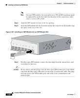
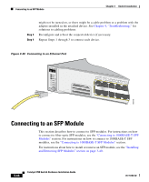
Chapter 3 Switch Installation Connecting to the 10/100 and 10/100/1000 Ports Follow these steps to connect to 10BASE-T, 100BASE-TX or 1000BASE-T devices: Caution To prevent electrostatic-discharge (ESD) damage, follow your normal board and component handling procedures. Step 1 When connecting to workstations, servers, routers, and Cisco IP Phones, connect a straight-through cable to an RJ-45 connector on the front panel. (See Figure 3-40.) When connecting to switches or repeaters, use a crossover cable. (See the "Cable and Adapter Specifications" section on page B-6 for cable-pinout descriptions.) Note When connecting to 1000BASE-T-compatible devices, be sure to use a twisted four-pair, Category 5 cable. Note On switches running Cisco IOS Release 12.1(14)EA1 or later, you can use the mdix auto command in the CLI to enable the automatic crossover feature. When the automatic crossover feature is enabled, the switch detects the required cable type for copper Ethernet connections and configures the interfaces accordingly. Therefore, you can use either a crossover or a straight-through cable for connections to a copper 10/100 or 10/100/1000 port on the switch, regardless the type of device on the other end of the connection. The automatic crossover feature is disabled by default. For configuration information for this feature, refer to the switch software configuration guide or the switch command reference. Step 2 Connect the other end of the cable to an RJ-45 connector on the other device. The port LED turns on when both the switch and the connected device have established link. The port LED is amber while Spanning Tree Protocol (STP) discovers the topology and searches for loops. This takes about 30 seconds, and then the port LED turns green. If the port LED does not turn on, the device at the other end 78-15136-02 Catalyst 3750 Switch Hardware Installation Guide 3-45
-
 1
1 -
2
-
3
-
4
-
5
-
6
-
7
-
8
-
9
-
10
-
11
-
12
-
13
-
14
-
15
-
16
-
17
-
18
-
19
-
20
-
21
-
22
-
23
-
24
-
25
-
26
-
27
-
28
-
29
-
30
-
31
-
32
-
33
-
34
-
35
-
36
-
37
-
38
-
39
-
40
-
41
-
42
-
43
-
44
-
45
-
46
-
47
-
48
-
49
-
50
-
51
-
52
-
53
-
54
-
55
-
56
-
57
-
58
-
59
-
60
-
61
-
62
-
63
-
64
-
65
-
66
-
67
-
68
-
69
-
70
-
71
-
72
-
73
-
74
-
75
-
76
-
77
-
78
-
79
-
80
-
81
-
82
-
83
-
84
-
85
-
86
-
87
-
88
-
89
-
90
-
91
-
92
-
93
-
94
-
95
-
96
-
97
-
98
-
99
-
 100
100 -
 101
101 -
 102
102 -
 103
103 -
 104
104 -
 105
105 -
 106
106 -
 107
107 -
 108
108 -
 109
109 -
 110
110 -
111
-
112
-
113
-
114
-
115
-
116
-
117
-
118
-
119
-
120
-
121
-
122
-
123
-
124
-
125
-
126
-
127
-
128
-
129
-
130
-
131
-
132
-
133
-
134
-
135
-
136
-
137
-
138
-
139
-
140
-
141
-
142
-
143
-
144
-
145
-
146
-
147
-
148
-
149
-
150
-
151
-
152
-
153
-
154
-
155
-
156
-
157
-
158
-
159
-
160
-
161
-
162
-
163
-
164
-
165
-
166
-
167
-
168
-
169
-
170
-
171
-
172
-
173
-
174
-
175
-
176
-
177
-
178
-
179
-
180
-
181
-
182
-
183
-
184
-
185
-
186
-
187
-
188
-
189
-
190
-
191
-
192
-
193
-
194
-
195
-
196
-
197
-
198
 |
 |