Cisco WS-C3750X-24T-L Hardware Installation Guide - Page 107
Connecting to a Fiber-Optic SFP Module
 |
View all Cisco WS-C3750X-24T-L manuals
Add to My Manuals
Save this manual to your list of manuals |
Page 107 highlights
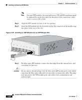
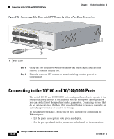
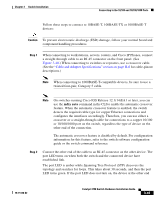
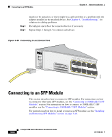
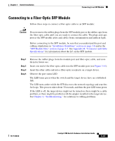
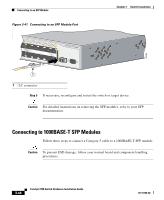
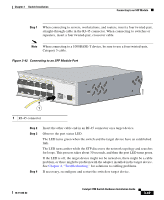
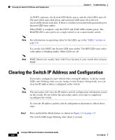
Chapter 3 Switch Installation Connecting to an SFP Module Connecting to a Fiber-Optic SFP Module Follow these steps to connect a fiber-optic cable to an SFP module: Caution Do not remove the rubber plugs from the SFP module port or the rubber caps from the fiber-optic cable until you are ready to connect the cable. The plugs and caps protect the SFP module ports and cables from contamination and ambient light. Before connecting to the SFP module, be sure that you understand the port and cabling stipulations in "Installation Guidelines" section on page 3-6 and in the "SFP Module Slots" section on page 2-7. See Appendix B, "Connector and Cable Specifications" for information about the LC on the SFP module. Step 1 Step 2 Step 3 Step 4 Remove the rubber plugs from the module port and fiber-optic cable, and store them for future use. Insert one end of the fiber-optic cable into the SFP module port (see Figure 3-41). Insert the other cable end into a fiber-optic receptacle on a target device. Observe the port status LED. The LED turns green when the switch and the target device have an established link. The LED turns amber while the STP discovers the network topology and searches for loops. This process takes about 30 seconds, and then the port LED turns green. If the LED is off, the target device might not be turned on, there might be a cable problem, or there might be problem with the adapter installed in the target device. See Chapter 4, "Troubleshooting," for solutions to cabling problems. 78-15136-02 Catalyst 3750 Switch Hardware Installation Guide 3-47
-
 1
1 -
2
-
3
-
4
-
5
-
6
-
7
-
8
-
9
-
10
-
11
-
12
-
13
-
14
-
15
-
16
-
17
-
18
-
19
-
20
-
21
-
22
-
23
-
24
-
25
-
26
-
27
-
28
-
29
-
30
-
31
-
32
-
33
-
34
-
35
-
36
-
37
-
38
-
39
-
40
-
41
-
42
-
43
-
44
-
45
-
46
-
47
-
48
-
49
-
50
-
51
-
52
-
53
-
54
-
55
-
56
-
57
-
58
-
59
-
60
-
61
-
62
-
63
-
64
-
65
-
66
-
67
-
68
-
69
-
70
-
71
-
72
-
73
-
74
-
75
-
76
-
77
-
78
-
79
-
80
-
81
-
82
-
83
-
84
-
85
-
86
-
87
-
88
-
89
-
90
-
91
-
92
-
93
-
94
-
95
-
96
-
97
-
98
-
99
-
100
-
101
-
 102
102 -
 103
103 -
 104
104 -
 105
105 -
 106
106 -
 107
107 -
 108
108 -
 109
109 -
 110
110 -
 111
111 -
 112
112 -
113
-
114
-
115
-
116
-
117
-
118
-
119
-
120
-
121
-
122
-
123
-
124
-
125
-
126
-
127
-
128
-
129
-
130
-
131
-
132
-
133
-
134
-
135
-
136
-
137
-
138
-
139
-
140
-
141
-
142
-
143
-
144
-
145
-
146
-
147
-
148
-
149
-
150
-
151
-
152
-
153
-
154
-
155
-
156
-
157
-
158
-
159
-
160
-
161
-
162
-
163
-
164
-
165
-
166
-
167
-
168
-
169
-
170
-
171
-
172
-
173
-
174
-
175
-
176
-
177
-
178
-
179
-
180
-
181
-
182
-
183
-
184
-
185
-
186
-
187
-
188
-
189
-
190
-
191
-
192
-
193
-
194
-
195
-
196
-
197
-
198
 |
 |