Cisco WS-C3750X-24T-L Hardware Installation Guide - Page 49
System LED, RPS LED, Color, System Status, RPS Status
 |
View all Cisco WS-C3750X-24T-L manuals
Add to My Manuals
Save this manual to your list of manuals |
Page 49 highlights
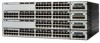
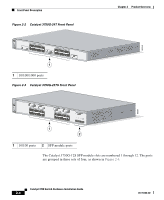
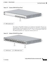
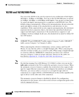
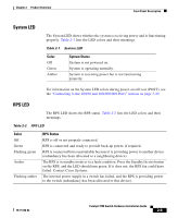
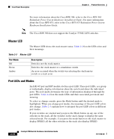
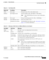
Chapter 2 Product Overview Front Panel Description System LED The System LED shows whether the system is receiving power and is functioning properly. Table 2-1 lists the LED colors and their meanings. Table 2-1 System LED Color Off Green Amber System Status System is not powered on. System is operating normally. System is receiving power but is not functioning properly. For information on the System LED colors during power-on self-test (POST), see the "Connecting to the 10/100 and 10/100/1000 Ports" section on page 3-44. RPS LED The RPS LED shows the RPS status. Table 2-2 lists the LED colors and their meanings. Table 2-2 RPS LED Color Off Green Flashing green Amber Flashing amber RPS Status RPS is off or not properly connected. RPS is connected and ready to provide back-up power, if required. RPS is connected but is unavailable because it is providing power to another device (redundancy has been allocated to a neighboring device). The RPS is in standby mode or in a fault condition. Press the Standby/Active button on the RPS, and the LED should turn green. If it does not, the RPS fan could have failed. Contact Cisco Systems. The internal power supply in a switch has failed, and the RPS is providing power to the switch (redundancy has been allocated to this device). 78-15136-02 Catalyst 3750 Switch Hardware Installation Guide 2-9
-
 1
1 -
2
-
3
-
4
-
5
-
6
-
7
-
8
-
9
-
10
-
11
-
12
-
13
-
14
-
15
-
16
-
17
-
18
-
19
-
20
-
21
-
22
-
23
-
24
-
25
-
26
-
27
-
28
-
29
-
30
-
31
-
32
-
33
-
34
-
35
-
36
-
37
-
38
-
39
-
40
-
41
-
42
-
43
-
 44
44 -
 45
45 -
 46
46 -
 47
47 -
 48
48 -
 49
49 -
 50
50 -
 51
51 -
 52
52 -
 53
53 -
 54
54 -
55
-
56
-
57
-
58
-
59
-
60
-
61
-
62
-
63
-
64
-
65
-
66
-
67
-
68
-
69
-
70
-
71
-
72
-
73
-
74
-
75
-
76
-
77
-
78
-
79
-
80
-
81
-
82
-
83
-
84
-
85
-
86
-
87
-
88
-
89
-
90
-
91
-
92
-
93
-
94
-
95
-
96
-
97
-
98
-
99
-
100
-
101
-
102
-
103
-
104
-
105
-
106
-
107
-
108
-
109
-
110
-
111
-
112
-
113
-
114
-
115
-
116
-
117
-
118
-
119
-
120
-
121
-
122
-
123
-
124
-
125
-
126
-
127
-
128
-
129
-
130
-
131
-
132
-
133
-
134
-
135
-
136
-
137
-
138
-
139
-
140
-
141
-
142
-
143
-
144
-
145
-
146
-
147
-
148
-
149
-
150
-
151
-
152
-
153
-
154
-
155
-
156
-
157
-
158
-
159
-
160
-
161
-
162
-
163
-
164
-
165
-
166
-
167
-
168
-
169
-
170
-
171
-
172
-
173
-
174
-
175
-
176
-
177
-
178
-
179
-
180
-
181
-
182
-
183
-
184
-
185
-
186
-
187
-
188
-
189
-
190
-
191
-
192
-
193
-
194
-
195
-
196
-
197
-
198
 |
 |