Cisco WS-C3750X-24T-L Hardware Installation Guide - Page 52
Port Mode, LED Color, Meaning, Stack LED
 |
View all Cisco WS-C3750X-24T-L manuals
Add to My Manuals
Save this manual to your list of manuals |
Page 52 highlights
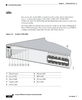
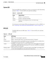
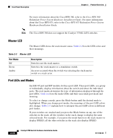
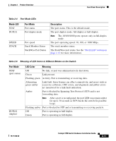
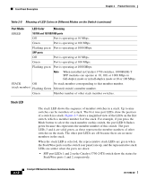
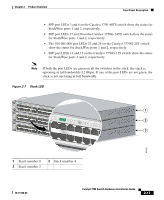
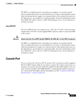
Front Panel Description Chapter 2 Product Overview Table 2-5 Meaning of LED Colors in Different Modes on the Switch (continued) Port Mode LED Color Meaning SPEED 10/100 and 10/100/1000 ports Off Port is operating at 10 Mbps. Green Port is operating at 100 Mbps. Flashing green Port is operating at 1000 Mbps. SFP ports Off Port is operating at 10 Mbps. Green Port is operating at 100 Mbps. Flashing green Port is operating at 1000 Mbps. Note When installed in Catalyst 3750 switches, 1000BASE-T SFP modules can operate at 10, 100, or 1000 Mbps in full-duplex mode or in half-duplex mode at 10 or 100 Mbps. STACK Off No stack member corresponding to that member number. (stack member) Flashing Green Selected switch's member number. Green Member number of other stack member switches. Stack LED The stack LED shows the sequence of member switches in a stack. Up to nine switches can be members of a stack. The first nine port LEDs show the position of a switch in a stack. Figure 2-7 shows a magnified view of the LEDs on the first switch, which is member number 8 of the stack. For example, if you press the Mode button to select the stack member on this switch, the port LED 8 flashes green because this represents the member number of this switch. The port LEDs 3 and 4 are solid green, as these represent the member numbers of other switches in the stack. The other port LEDs are off because there are no more members in the stack. When the stack LED is selected, the representative stack LEDs are green when the StackWise ports (on the switch rear panel) are up, and the representative stack LEDs are amber when the ports are down: • SFP port LEDs 1 and 2 on the Catalyst 3750-24TS switch show the status for StackWise ports 1 and 2, respectively. 2-12 Catalyst 3750 Switch Hardware Installation Guide 78-15136-02
-
 1
1 -
2
-
3
-
4
-
5
-
6
-
7
-
8
-
9
-
10
-
11
-
12
-
13
-
14
-
15
-
16
-
17
-
18
-
19
-
20
-
21
-
22
-
23
-
24
-
25
-
26
-
27
-
28
-
29
-
30
-
31
-
32
-
33
-
34
-
35
-
36
-
37
-
38
-
39
-
40
-
41
-
42
-
43
-
44
-
45
-
46
-
 47
47 -
 48
48 -
 49
49 -
 50
50 -
 51
51 -
 52
52 -
 53
53 -
 54
54 -
 55
55 -
 56
56 -
 57
57 -
58
-
59
-
60
-
61
-
62
-
63
-
64
-
65
-
66
-
67
-
68
-
69
-
70
-
71
-
72
-
73
-
74
-
75
-
76
-
77
-
78
-
79
-
80
-
81
-
82
-
83
-
84
-
85
-
86
-
87
-
88
-
89
-
90
-
91
-
92
-
93
-
94
-
95
-
96
-
97
-
98
-
99
-
100
-
101
-
102
-
103
-
104
-
105
-
106
-
107
-
108
-
109
-
110
-
111
-
112
-
113
-
114
-
115
-
116
-
117
-
118
-
119
-
120
-
121
-
122
-
123
-
124
-
125
-
126
-
127
-
128
-
129
-
130
-
131
-
132
-
133
-
134
-
135
-
136
-
137
-
138
-
139
-
140
-
141
-
142
-
143
-
144
-
145
-
146
-
147
-
148
-
149
-
150
-
151
-
152
-
153
-
154
-
155
-
156
-
157
-
158
-
159
-
160
-
161
-
162
-
163
-
164
-
165
-
166
-
167
-
168
-
169
-
170
-
171
-
172
-
173
-
174
-
175
-
176
-
177
-
178
-
179
-
180
-
181
-
182
-
183
-
184
-
185
-
186
-
187
-
188
-
189
-
190
-
191
-
192
-
193
-
194
-
195
-
196
-
197
-
198
 |
 |