Cisco WS-C3750X-24T-L Hardware Installation Guide - Page 57
Console Port, Cisco RPS 675
 |
View all Cisco WS-C3750X-24T-L manuals
Add to My Manuals
Save this manual to your list of manuals |
Page 57 highlights
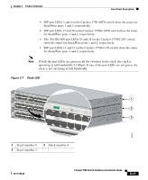
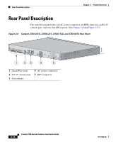
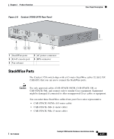
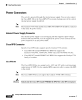
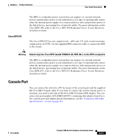
Chapter 2 Product Overview Rear Panel Description Cisco RPS 675 The RPS is a redundant power system that can support six external network devices and provides power to one failed device at a time. It automatically senses when the internal power supply of a connected device fails and provides power to the failed device, preventing loss of network traffic. For more information on the Cisco RPS 300, refer to the Cisco RPS 300 Redundant Power System Hardware Installation Guide. The Cisco RPS 675 has two output levels: -48V and 12V with a total maximum output power of 675W. Use the supplied RPS connector cable to connect the RPS to the switch. Warning Attach only the Cisco RPS (model PWR675-AC-RPS-N1=) to the RPS receptacle. The RPS is a redundant power system that can support six external network devices and provides power to one failed device at a time. It automatically senses when the internal power supply of a connected device fails and provides power to the failed device, preventing loss of network traffic. For more information on the Cisco RPS 675, refer to the Cisco RPS 675 Redundant Power System Hardware Installation Guide. Console Port You can connect the switch to a PC by means of the console port and the supplied RJ-45-to-DB-9 female cable. If you want to connect the switch console port to a terminal, you need to provide an RJ-45-to-DB-25 female DTE adapter. You can order a kit (part number ACS-DSBUASYN=) containing that adapter from Cisco. For console port and adapter pinout information, see the "Connector and Cable Specifications" section on page B-1. 78-15136-02 Catalyst 3750 Switch Hardware Installation Guide 2-17
-
 1
1 -
2
-
3
-
4
-
5
-
6
-
7
-
8
-
9
-
10
-
11
-
12
-
13
-
14
-
15
-
16
-
17
-
18
-
19
-
20
-
21
-
22
-
23
-
24
-
25
-
26
-
27
-
28
-
29
-
30
-
31
-
32
-
33
-
34
-
35
-
36
-
37
-
38
-
39
-
40
-
41
-
42
-
43
-
44
-
45
-
46
-
47
-
48
-
49
-
50
-
51
-
 52
52 -
 53
53 -
 54
54 -
 55
55 -
 56
56 -
 57
57 -
 58
58 -
 59
59 -
 60
60 -
 61
61 -
 62
62 -
63
-
64
-
65
-
66
-
67
-
68
-
69
-
70
-
71
-
72
-
73
-
74
-
75
-
76
-
77
-
78
-
79
-
80
-
81
-
82
-
83
-
84
-
85
-
86
-
87
-
88
-
89
-
90
-
91
-
92
-
93
-
94
-
95
-
96
-
97
-
98
-
99
-
100
-
101
-
102
-
103
-
104
-
105
-
106
-
107
-
108
-
109
-
110
-
111
-
112
-
113
-
114
-
115
-
116
-
117
-
118
-
119
-
120
-
121
-
122
-
123
-
124
-
125
-
126
-
127
-
128
-
129
-
130
-
131
-
132
-
133
-
134
-
135
-
136
-
137
-
138
-
139
-
140
-
141
-
142
-
143
-
144
-
145
-
146
-
147
-
148
-
149
-
150
-
151
-
152
-
153
-
154
-
155
-
156
-
157
-
158
-
159
-
160
-
161
-
162
-
163
-
164
-
165
-
166
-
167
-
168
-
169
-
170
-
171
-
172
-
173
-
174
-
175
-
176
-
177
-
178
-
179
-
180
-
181
-
182
-
183
-
184
-
185
-
186
-
187
-
188
-
189
-
190
-
191
-
192
-
193
-
194
-
195
-
196
-
197
-
198
 |
 |