Cisco WS-C3750X-24T-L Hardware Installation Guide - Page 66
Installation Guidelines, SFP Module, Wavelength, nanometers, Fiber Type, Core Size, micron, Modal
 |
View all Cisco WS-C3750X-24T-L manuals
Add to My Manuals
Save this manual to your list of manuals |
Page 66 highlights
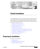
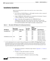
Preparing for Installation Chapter 3 Switch Installation Installation Guidelines When determining where to place the switch, be sure to observe these requirements: • For 10/100 and 10/100/1000 ports, cable lengths from the switch to connected devices are up to 328 feet (100 meters). • Copper 1000BASE-T SFP modules use standard four twisted-pair, Category 5 cable at lengths up to 328 feet (100 meters). • Table 3-1 lists the cable specifications for 1000BASE-SX and 1000BASE-LX fiber-optic SFP connections. Each port must match the wave-length specifications on the other end of the cable, and the cable must not exceed the stipulated cable length for reliable communications. Table 3-1 Fiber-Optic SFP Module Port Cabling Specifications SFP Module Wavelength (nanometers) Fiber Type Core Size (micron) Modal Bandwidth (MHz/km) Cable Distance 1000BASE-SX 850 1000BASE-LX/LH 1300 MMF 62.5 160 62.5 200 50.0 400 50.0 500 MMF1 62.5 500 50.0 400 SMF 50.0 500 9/10 - 722 feet (220 m) 902 feet (275 m) 1640 feet (500 m) 1804 feet (550 m) 1804 feet (550 m) 1804 feet (550 m) 1804 feet (550 m) 32,810 feet (10 km) 1. A mode-conditioning patch cord is required. Using an ordinary patch cord with MMF, 1000BASE-LX/LH SFP modules, and a short link distance can cause transceiver saturation, resulting in an elevated bit error rate (BER). When using the LX/LH SFP module with 62.5-micron diameter MMF, you must also install a mode-conditioning patch cord between the SFP module and the MMF cable on both the sending and receiving ends of the link. The mode-conditioning patch cord is required for link distances greater than 984 feet (300 m). • Operating environment is within the ranges listed in Appendix A, "Technical Specifications." • Clearance to front and rear panels is such that - Front-panel indicators can be easily read. - Access to ports is sufficient for unrestricted cabling. Catalyst 3750 Switch Hardware Installation Guide 3-6 78-15136-02
-
 1
1 -
2
-
3
-
4
-
5
-
6
-
7
-
8
-
9
-
10
-
11
-
12
-
13
-
14
-
15
-
16
-
17
-
18
-
19
-
20
-
21
-
22
-
23
-
24
-
25
-
26
-
27
-
28
-
29
-
30
-
31
-
32
-
33
-
34
-
35
-
36
-
37
-
38
-
39
-
40
-
41
-
42
-
43
-
44
-
45
-
46
-
47
-
48
-
49
-
50
-
51
-
52
-
53
-
54
-
55
-
56
-
57
-
58
-
59
-
60
-
 61
61 -
 62
62 -
 63
63 -
 64
64 -
 65
65 -
 66
66 -
 67
67 -
 68
68 -
 69
69 -
 70
70 -
 71
71 -
72
-
73
-
74
-
75
-
76
-
77
-
78
-
79
-
80
-
81
-
82
-
83
-
84
-
85
-
86
-
87
-
88
-
89
-
90
-
91
-
92
-
93
-
94
-
95
-
96
-
97
-
98
-
99
-
100
-
101
-
102
-
103
-
104
-
105
-
106
-
107
-
108
-
109
-
110
-
111
-
112
-
113
-
114
-
115
-
116
-
117
-
118
-
119
-
120
-
121
-
122
-
123
-
124
-
125
-
126
-
127
-
128
-
129
-
130
-
131
-
132
-
133
-
134
-
135
-
136
-
137
-
138
-
139
-
140
-
141
-
142
-
143
-
144
-
145
-
146
-
147
-
148
-
149
-
150
-
151
-
152
-
153
-
154
-
155
-
156
-
157
-
158
-
159
-
160
-
161
-
162
-
163
-
164
-
165
-
166
-
167
-
168
-
169
-
170
-
171
-
172
-
173
-
174
-
175
-
176
-
177
-
178
-
179
-
180
-
181
-
182
-
183
-
184
-
185
-
186
-
187
-
188
-
189
-
190
-
191
-
192
-
193
-
194
-
195
-
196
-
197
-
198
 |
 |