Cisco WS-C3750X-24T-L Hardware Installation Guide - Page 71
Powering Off the Switch and Disconnecting the Console Port
 |
View all Cisco WS-C3750X-24T-L manuals
Add to My Manuals
Save this manual to your list of manuals |
Page 71 highlights
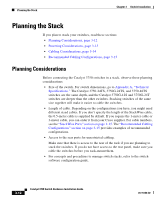
Chapter 3 Switch Installation Preparing for Installation Step 3 Connect the other end of the power cord to an AC power outlet. If you are installing the Catalyst 3750-24TS, 3750G-24T, 3750G-12S, or 3750-48TS switches, you can use the Cisco RPS 300. Warning Attach only the Cisco RPS 300 (model PWR300-AC-RPS-N1) to the RPS receptacle If you are installing the Catalyst 3750-24TS, 3750G-24T, 3750G-24T, 3750G-12S, or 3750-48TS switches, you can use the Cisco RPS 675. Warning Attach only the Cisco RPS 675 (model PWR675-AC-RPS-N1=) to the RPS receptacle As the switch powers on, it begins POST, a series of tests that run automatically to ensure that the switch functions properly. When the switch begins POST, the System, the RPS, the Master, the Status, the Duplex LEDs turn amber for 2 seconds. The Speed and the Stack LEDs turn green for 2 seconds. As POST continues, the System LED flashes green, and the other LEDs turn off. The port LEDs turn solid green, and each port LED turns off as the test successfully checks each port. If there is a failure associated with a particular port, that port LED turns amber, and the system LED turns amber. When POST is complete, only the SYST and STAT LEDs are green. The MASTR LED is also green on a single switch or on a stack master switch. If a switch fails POST, the System LED turns amber. The RPS LED turns either solid amber or blinking amber. Other LEDs are off. If POST fails, see Chapter 4, "Troubleshooting," to determine a course of action. Powering Off the Switch and Disconnecting the Console Port Disconnect the power cord from the switch. Disconnect the cable from the switch console port. Install the switch in a rack, on a wall, or on a table or shelf as described in the "Installing the Switch" section on page 3-17. 78-15136-02 Catalyst 3750 Switch Hardware Installation Guide 3-11
-
 1
1 -
2
-
3
-
4
-
5
-
6
-
7
-
8
-
9
-
10
-
11
-
12
-
13
-
14
-
15
-
16
-
17
-
18
-
19
-
20
-
21
-
22
-
23
-
24
-
25
-
26
-
27
-
28
-
29
-
30
-
31
-
32
-
33
-
34
-
35
-
36
-
37
-
38
-
39
-
40
-
41
-
42
-
43
-
44
-
45
-
46
-
47
-
48
-
49
-
50
-
51
-
52
-
53
-
54
-
55
-
56
-
57
-
58
-
59
-
60
-
61
-
62
-
63
-
64
-
65
-
 66
66 -
 67
67 -
 68
68 -
 69
69 -
 70
70 -
 71
71 -
 72
72 -
 73
73 -
 74
74 -
 75
75 -
 76
76 -
77
-
78
-
79
-
80
-
81
-
82
-
83
-
84
-
85
-
86
-
87
-
88
-
89
-
90
-
91
-
92
-
93
-
94
-
95
-
96
-
97
-
98
-
99
-
100
-
101
-
102
-
103
-
104
-
105
-
106
-
107
-
108
-
109
-
110
-
111
-
112
-
113
-
114
-
115
-
116
-
117
-
118
-
119
-
120
-
121
-
122
-
123
-
124
-
125
-
126
-
127
-
128
-
129
-
130
-
131
-
132
-
133
-
134
-
135
-
136
-
137
-
138
-
139
-
140
-
141
-
142
-
143
-
144
-
145
-
146
-
147
-
148
-
149
-
150
-
151
-
152
-
153
-
154
-
155
-
156
-
157
-
158
-
159
-
160
-
161
-
162
-
163
-
164
-
165
-
166
-
167
-
168
-
169
-
170
-
171
-
172
-
173
-
174
-
175
-
176
-
177
-
178
-
179
-
180
-
181
-
182
-
183
-
184
-
185
-
186
-
187
-
188
-
189
-
190
-
191
-
192
-
193
-
194
-
195
-
196
-
197
-
198
 |
 |