Cisco WS-C3750X-24T-L Hardware Installation Guide - Page 94
Mounting the Switch on a Wall,
 |
View all Cisco WS-C3750X-24T-L manuals
Add to My Manuals
Save this manual to your list of manuals |
Page 94 highlights
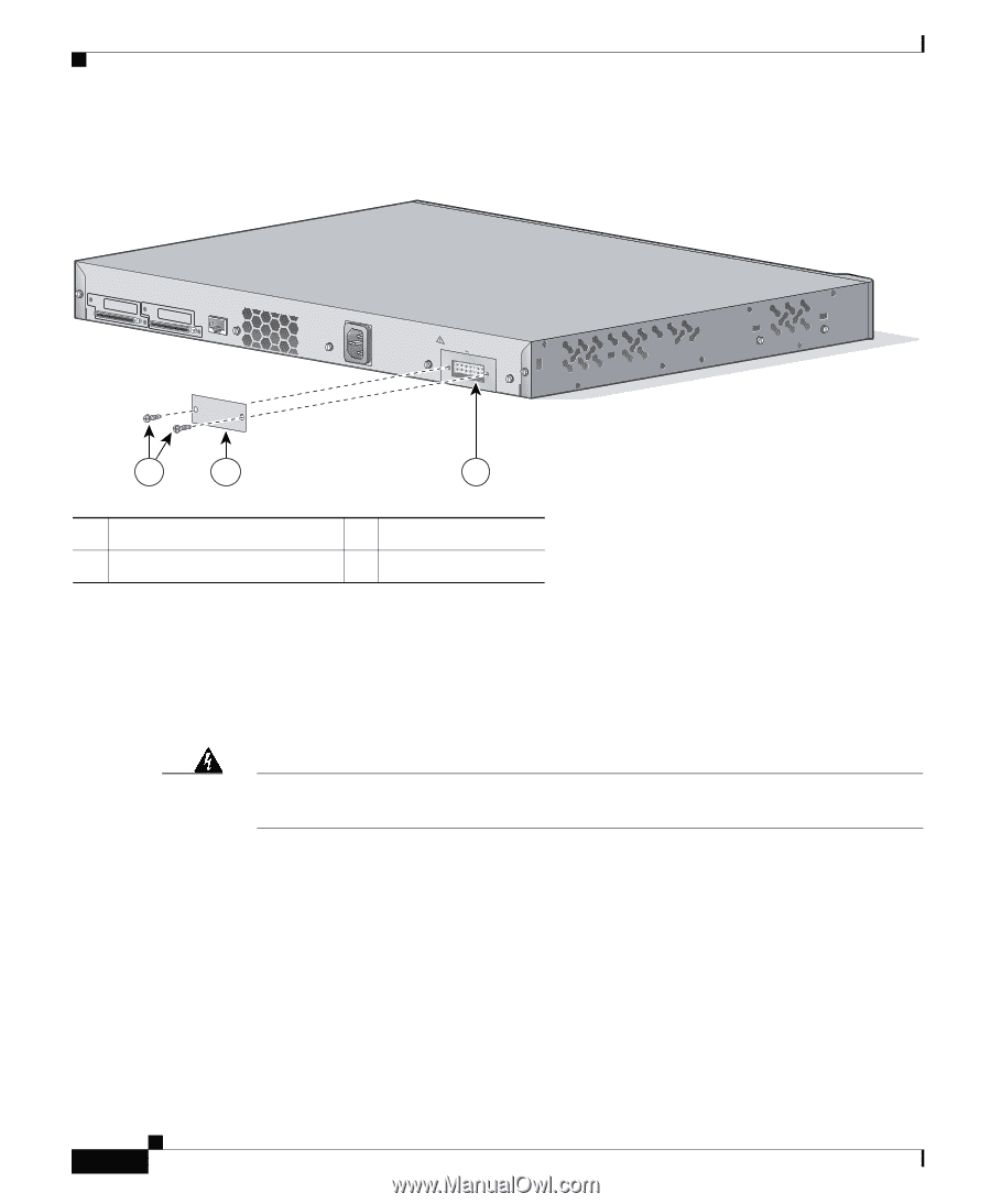
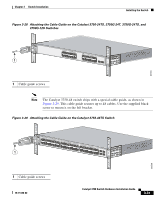
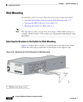
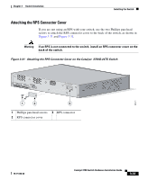
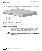
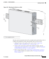
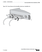
Installing the Switch Chapter 3 Switch Installation Figure 3-32 Attaching the RPS Connector Cover on the Catalyst 3750G-12S, 3750-24TS, 3750G-24T, and the 3750-48TS Switches STACK 1 STACK 2 CONSOLE 1.6A-100R>09A-A2T0,IN05GV0-~60 HZ [email protected] 1 2 3 1 Phillips pan-head screws 3 RPS connector 2 RPS connector cover Mounting the Switch on a Wall For the best support of the switch and cables, make sure the switch is attached securely to wall studs or to a firmly attached plywood mounting backboard. Mount the switch with the front panel facing up, as shown in Figure 3-33. Warning To comply with safety regulations, mount the switches on a wall with the front panel facing up. 86572 3-34 Catalyst 3750 Switch Hardware Installation Guide 78-15136-02
-
 1
1 -
2
-
3
-
4
-
5
-
6
-
7
-
8
-
9
-
10
-
11
-
12
-
13
-
14
-
15
-
16
-
17
-
18
-
19
-
20
-
21
-
22
-
23
-
24
-
25
-
26
-
27
-
28
-
29
-
30
-
31
-
32
-
33
-
34
-
35
-
36
-
37
-
38
-
39
-
40
-
41
-
42
-
43
-
44
-
45
-
46
-
47
-
48
-
49
-
50
-
51
-
52
-
53
-
54
-
55
-
56
-
57
-
58
-
59
-
60
-
61
-
62
-
63
-
64
-
65
-
66
-
67
-
68
-
69
-
70
-
71
-
72
-
73
-
74
-
75
-
76
-
77
-
78
-
79
-
80
-
81
-
82
-
83
-
84
-
85
-
86
-
87
-
88
-
 89
89 -
 90
90 -
 91
91 -
 92
92 -
 93
93 -
 94
94 -
 95
95 -
 96
96 -
 97
97 -
 98
98 -
 99
99 -
100
-
101
-
102
-
103
-
104
-
105
-
106
-
107
-
108
-
109
-
110
-
111
-
112
-
113
-
114
-
115
-
116
-
117
-
118
-
119
-
120
-
121
-
122
-
123
-
124
-
125
-
126
-
127
-
128
-
129
-
130
-
131
-
132
-
133
-
134
-
135
-
136
-
137
-
138
-
139
-
140
-
141
-
142
-
143
-
144
-
145
-
146
-
147
-
148
-
149
-
150
-
151
-
152
-
153
-
154
-
155
-
156
-
157
-
158
-
159
-
160
-
161
-
162
-
163
-
164
-
165
-
166
-
167
-
168
-
169
-
170
-
171
-
172
-
173
-
174
-
175
-
176
-
177
-
178
-
179
-
180
-
181
-
182
-
183
-
184
-
185
-
186
-
187
-
188
-
189
-
190
-
191
-
192
-
193
-
194
-
195
-
196
-
197
-
198
 |
 |