Cobra 25 LTD 25LTDST
Cobra 25 LTD Manual
 |
View all Cobra 25 LTD manuals
Add to My Manuals
Save this manual to your list of manuals |
Cobra 25 LTD manual content summary:
- Cobra 25 LTD | 25LTDST - Page 1
OPERATING INSTRUCTIONS FOR YOUR 40 CHANNEL CITIZENS BAND 2-WAY MOBILE RADIO Model 25 LTD ST Cobra Electronics Corporation 6500 W. Cortland Street Chicago, IL 60707 PRINTED IN HONG KONG ©COBRA ELECTRONICS CORP. 1997 480-205-P-001 - Cobra 25 LTD | 25LTDST - Page 2
Radio Model 25 LTD ST Contents Page The CB Story 1 SoundTracker System 1 Specifications 2,3 Installation Location 4 Mounting Connections 4, 5 CB Antenna 6 Ignition Noise Interference 7 In House Operation 7 Operation Controls and Indicators 8, 9, 10 Operating Procedure to Receive - Cobra 25 LTD | 25LTDST - Page 3
FREQUENCY RANGE The COBRA 25 LTD ST transceiver represents one of the most advanced AM twoway radios ever designed for use as a Class D station in the Citizens Radio Service. This unit features advanced Phase Lock Loop (PLL) circuitry providing complete coverage of all 40 channels as shown below - Cobra 25 LTD | 25LTDST - Page 4
holes and secure mounting bracket in location. Installation (Cont.) 3. Connect the antenna cable plug to the standard receptacle on the unit. Most CB antennas are terminated with a type PL-259 plug which mates with the receptacle marked "ANT." 4. Connect the red lead of DC power cord to +13.8 VDC - Cobra 25 LTD | 25LTDST - Page 5
not present a serious problem. Also, when extremely low level signals are being received, the transceiver may be operated with vehicle engine turned off. The unit requires very little current and therefore will not significantly discharge the vehicle battery. Even though the COBRA 25 LTD ST has an - Cobra 25 LTD | 25LTDST - Page 6
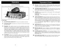
instant selection of emer- gency Channel 9 (CH. 9 position) or information Channel 19. In NORMAL position, all 40 CB channels can be accessed by the CHANNEL SELECTOR switch. 12. RX/TX LED INDICATOR. When your radio is in the CB receive mode, the LED will be green. When in transmit mode, the LED will - Cobra 25 LTD | 25LTDST - Page 7
to Receive 1. Be sure that the power cord, antenna and microphone are connected to the proper connectors before proceeding further. The PA/CB should be in the CB position. 2. Turn the radio ON by rotating the VOLUME CONTROL clockwise. 3. Set the RF GAIN CONTROL fully clockwise. 4. Set DELTA-TUNE - Cobra 25 LTD | 25LTDST - Page 8
-to-talk switch on the microphone. Press the switch and the transmitter is activated; release switch to receive. When transmitting (on a clear channel), hold the microphone two inches from the mouth and speak clearly in a normal voice. Be sure the antenna is properly connected to the radio before - Cobra 25 LTD | 25LTDST - Page 9
, review the following, then if necessary, replace parts only with identical parts. Do not substitute. Refer to the schematic diagram and parts. 1. Check connections to the source of power and make sure it is the 13.8 VDC required to operate your radio. 2. Check the fuse in the DC power cord. The - Cobra 25 LTD | 25LTDST - Page 10
loss in transit) such as United Parcel Service (UPS), Roadway Parcel Service (RPS) or First Class Insured Mail to Cobra Factory Service, Cobra Electronics Corporation, 6500 W. Cortland St., Chicago, IL 60707. Cobra is not responsible for units not received if package has not been properly insured - Cobra 25 LTD | 25LTDST - Page 11
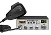
fine accessories at your local Cobra CB dealer. Description Part No. DYNAMIC MICROPHONE Replacement microphone with 4-pin screw-on connector CA-73 DC POWER CORD Exact replacement 426-002-N-001 MOUNTING BRACKET Exact replacement 251-199-9-001 MOUNTING BRACKET SCREWS Exact replacements 634
-
 1
1 -
 2
2 -
 3
3 -
 4
4 -
 5
5 -
 6
6 -
 7
7 -
8
-
9
-
10
-
11
 |
 |

OPERATING INSTRUCTIONS FOR YOUR
40 CHANNEL
CITIZENS BAND
2-WAY MOBILE RADIO
Model
25 LTD ST
Cobra Electronics Corporation
6500 W. Cortland Street
Chicago, IL 60707
PRINTED IN HONG KONG
©COBRA ELECTRONICS CORP. 1997
480-205-P-001