Compaq 326 Compaq 325 and 326 Notebook PCs HP 425 and 625 Notebook PCs - Maint
Compaq 326 - Notebook PC Manual
 |
View all Compaq 326 manuals
Add to My Manuals
Save this manual to your list of manuals |
Compaq 326 manual content summary:
- Compaq 326 | Compaq 325 and 326 Notebook PCs HP 425 and 625 Notebook PCs - Maint - Page 1
Compaq 325 and 326 Notebook PCs HP 425 and 625 Notebook PCs Maintenance and Service Guide - Compaq 326 | Compaq 325 and 326 Notebook PCs HP 425 and 625 Notebook PCs - Maint - Page 2
Hewlett-Packard Development Company, L.P. AMD Athlon, AMD Sempron, and AMD Turion are trademarks of Advanced HP products and services are set forth in the express warranty statements accompanying such products and services. Nothing herein should be construed as constituting an additional warranty. HP - Compaq 326 | Compaq 325 and 326 Notebook PCs HP 425 and 625 Notebook PCs - Maint - Page 3
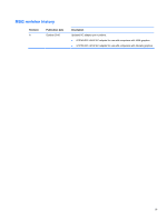
MSG revision history Revision A Publication date October 2010 Description Updated AC adapter part numbers: ● 613149-001-65-W AC adapter for use with computers with UMA graphics ● 613150-001-90-W AC adapter for use with computers with discrete graphics iii - Compaq 326 | Compaq 325 and 326 Notebook PCs HP 425 and 625 Notebook PCs - Maint - Page 4
iv MSG revision history - Compaq 326 | Compaq 325 and 326 Notebook PCs HP 425 and 625 Notebook PCs - Maint - Page 5
Safety warning notice WARNING! To reduce the possibility of heat-related injuries or of overheating the computer, do not place the computer directly on your lap or obstruct the computer air vents. Use the computer only on a hard, flat surface. Do not allow another hard surface, such as an adjoining - Compaq 326 | Compaq 325 and 326 Notebook PCs HP 425 and 625 Notebook PCs - Maint - Page 6
vi Safety warning notice - Compaq 326 | Compaq 325 and 326 Notebook PCs HP 425 and 625 Notebook PCs - Maint - Page 7
components ...17 Multimedia components ...19 Wireless antennas (select models only 20 Additional hardware components ...21 3 Illustrated parts catalog ...22 Service tag ...22 Computer major components ...23 Display assembly components ...29 Plastics Kit ...30 Cables ...31 Mass storage devices ...33 - Compaq 326 | Compaq 325 and 326 Notebook PCs HP 425 and 625 Notebook PCs - Maint - Page 8
Palm rest ...64 Keyboard ...67 Top cover ...71 Power switch board ...76 Bluetooth module ...78 USB connector assembly 79 Speaker ...81 Display assembly ...82 System board ...90 Main battery connector ...94 RTC battery ...96 Modem module ...97 Audio board ...99 5 Computer Setup ...101 Computer Setup - Compaq 326 | Compaq 325 and 326 Notebook PCs HP 425 and 625 Notebook PCs - Maint - Page 9
specifications 116 35.6-cm (14.0-in) display specifications 117 33.8-cm (13.3-in) display specifications 118 Hard drive specifications ...119 DVD-ROM Drive specifications ...120 DVD±RW Double-Layer Combo Drive specifications 129 Backup and recovery in Windows XP 130 Overview ...130 Backing up - Compaq 326 | Compaq 325 and 326 Notebook PCs HP 425 and 625 Notebook PCs - Maint - Page 10
...133 HDMI ...134 RJ-11 (modem) ...135 RJ-45 (network) ...136 Universal Serial Bus ...136 9 Power cord set requirements ...137 Requirements for all countries and regions 137 Requirements for specific countries and regions 138 10 Recycling ...139 Battery ...139 Display ...139 Index ...145 x - Compaq 326 | Compaq 325 and 326 Notebook PCs HP 425 and 625 Notebook PCs - Maint - Page 11
1 Product description Category Product Name Processors Chipsets Graphics Panels Description Compaq 325 model, UMA graphics, RS880M chipset Compaq 325 Notebook PC √ Compaq 326 Notebook PC HP 425 Notebook PC HP 625 Notebook PC AMD processors AMD Turion™ II Dual-Core P520 2.30-GHz √ with 2-MB - Compaq 326 | Compaq 325 and 326 Notebook PCs HP 425 and 625 Notebook PCs - Maint - Page 12
slots Supports dual-channel memory √ Supports up to 8 GB of system RAM √ PC3-10600, 1333-MHz, DDR3 √ Supports the 2, dual-channel) ● 1024-MB total system memory (1024MB × 1) Compaq 326 model, Discrete graphics, RS880MD chipset HP 425/625 models, UMA graphics, RS880M chipset √ √ √ √ √ - Compaq 326 | Compaq 325 and 326 Notebook PCs HP 425 and 625 Notebook PCs - Maint - Page 13
3.8 cm (1.5-in) data/fax modem Supports no modem option For use in all countries and regions except APJ For use in APJ only Modem cable not included Compaq 325 model, UMA graphics, RS880M chipset Compaq 326 model, Discrete graphics, RS880MD chipset HP 425/625 models, UMA graphics, RS880M - Compaq 326 | Compaq 325 and 326 Notebook PCs HP 425 and 625 Notebook PCs - Maint - Page 14
Ports Description Compaq 325 model, UMA graphics, RS880M chipset Compaq 326 model, Discrete graphics, RS880MD chipset HP 425/625 802.11 b/g/n (1 x 1) Integrated wireless personal area network (WPAN) options by way of Bluetooth® module: Support option for no-WPAN √ √ √ Bluetooth 2.1 - Compaq 326 | Compaq 325 and 326 Notebook PCs HP 425 and 625 Notebook PCs - Maint - Page 15
Power requirements Security Operating system Description 39.6-cm (15.6-in) keyboard with TouchPad Compaq 325 model, UMA graphics, RS880M chipset √ Compaq 326 model, Discrete graphics, RS880MD chipset HP Li-ion battery √ √ √ 9-cell, 93-Wh Li-ion battery √ √ √ Supports Kensington security - Compaq 326 | Compaq 325 and 326 Notebook PCs HP 425 and 625 Notebook PCs - Maint - Page 16
(with XP Pro √ images) (Japan only) Preinstalled: FreeDOS √ RedFlag Linux (People's Republic of China √ only) SuSE Linux √ Restore media: Windows 7 Home Basic 32 √ Windows 7 Home Premium 32 √ Windows 7 Home Premium 64 √ Compaq 326 model, Discrete graphics, RS880MD chipset HP 425/625 - Compaq 326 | Compaq 325 and 326 Notebook PCs HP 425 and 625 Notebook PCs - Maint - Page 17
Support: All Windows Vista 64 versions √ Windows 7 Professional 64 versions √ SuSE Linux √ End-user replaceable parts: AC adapter √ Battery (system) √ Hard drive √ Memory module √ Keyboard √ Optical drive √ WLAN module √ Compaq 326 model, Discrete graphics, RS880MD chipset HP - Compaq 326 | Compaq 325 and 326 Notebook PCs HP 425 and 625 Notebook PCs - Maint - Page 18
Top components TouchPad Component (1) TouchPad (2) TouchPad button (3) TouchPad scroll zone Description Moves the pointer and selects or activates items on the screen. The left and right sides of the single button function like the left and right buttons on an external mouse. Scrolls up or - Compaq 326 | Compaq 325 and 326 Notebook PCs HP 425 and 625 Notebook PCs - Maint - Page 19
Lights NOTE: Refer to the illustration that most closely matches your computer. Component (1) Caps lock light Description On: Caps lock is on. Top components 9 - Compaq 326 | Compaq 325 and 326 Notebook PCs HP 425 and 625 Notebook PCs - Maint - Page 20
(2) Power light (3) Wireless light Description ● On: The computer is on. ● Blinking: The computer is in the Sleep state in Windows 7 or Windows Vista, or in Standby in Windows XP. ● Off: The computer is off or in Hibernation. ● White: An integrated wireless device, such as a wireless local area - Compaq 326 | Compaq 325 and 326 Notebook PCs HP 425 and 625 Notebook PCs - Maint - Page 21
Produces sound. Turns off the display if the panel lid is closed while the power is on. ● When the computer is off, press the button to turn on and Windows shutdown procedures are ineffective, press and hold the power button for at least 5 seconds to turn off the computer. Top components 11 - Compaq 326 | Compaq 325 and 326 Notebook PCs HP 425 and 625 Notebook PCs - Maint - Page 22
Keys NOTE: Refer to the illustration and table that most closely matches your computer. Component (1) esc key (2) fn key (3) Windows logo key (4) Windows applications key (5) Embedded numeric keypad keys (6) Function keys (7) Wireless key Description Displays system information when pressed in - Compaq 326 | Compaq 325 and 326 Notebook PCs HP 425 and 625 Notebook PCs - Maint - Page 23
Component (1) esc key (2) fn key (3) Windows logo key (4) Windows applications key (5) Embedded numeric keypad keys (6) Wireless key (7) Function keys Description Displays system information when pressed in combination with the fn key. Executes frequently used system functions when pressed in - Compaq 326 | Compaq 325 and 326 Notebook PCs HP 425 and 625 Notebook PCs - Maint - Page 24
Component (1) SD Card Reader (2) Audio-out (headphone) jack (3) Audio-in (microphone) jack Description Supports the following optional digital card Produces sound when connected to optional powered stereo speakers, headphones, ear buds, a headset, or television audio. NOTE: When a device is - Compaq 326 | Compaq 325 and 326 Notebook PCs HP 425 and 625 Notebook PCs - Maint - Page 25
Right-side components Component (1) USB ports (2) (2) RJ-11 (modem) jack (select models only) (3) Optical drive (select models only) (4) Optical drive light (select models only) (5) Optical drive button (select models only) Description Connect optional USB devices. Connects a modem cable - Compaq 326 | Compaq 325 and 326 Notebook PCs HP 425 and 625 Notebook PCs - Maint - Page 26
Component (1) ExpressCard slot (2) Security cable slot (3) Vent (4) External monitor port (5) Battery light (6) Power connector (7) RJ-45 (network) jack (8) HDMI port (9) USB port (1) Description Supports optional ExpressCards. Attaches an optional security cable to the computer - Compaq 326 | Compaq 325 and 326 Notebook PCs HP 425 and 625 Notebook PCs - Maint - Page 27
Bottom components NOTE: Refer to the illustration that most closely matches your computer. Component (1) Battery release latches (2) Description Release the battery from the battery bay. Bottom components 17 - Compaq 326 | Compaq 325 and 326 Notebook PCs HP 425 and 625 Notebook PCs - Maint - Page 28
module compartment WLAN module compartment Hard drive bay Description Holds the battery. Enable airflow to cool internal components. NOTE: The computer computer functionality, and then contact technical support through Help and Support. Holds the hard drive. 18 Chapter 2 External - Compaq 326 | Compaq 325 and 326 Notebook PCs HP 425 and 625 Notebook PCs - Maint - Page 29
is in use. Records video and captures still photographs. Records sound. Produces sound when connected to optional powered stereo speakers, headphones, ear buds, a headset, or television audio. NOTE: When a device is connected to the headphone jack, the computer speakers are disabled. Connects an - Compaq 326 | Compaq 325 and 326 Notebook PCs HP 425 and 625 Notebook PCs - Maint - Page 30
from the outside of the computer. NOTE: For optimal transmission, keep the areas immediately around the antennas free from obstructions. Component Description WLAN antennas (2)* Send or region. These notices are located in Help and Support. 20 Chapter 2 External component identification - Compaq 326 | Compaq 325 and 326 Notebook PCs HP 425 and 625 Notebook PCs - Maint - Page 31
Additional hardware components Component Description (1) Power cord* Connects an AC adapter to an AC outlet. (2) AC adapter Converts AC power to DC power. (3) Battery* Powers the computer when the computer is not plugged into external power. *Batteries and power cords vary in appearance by - Compaq 326 | Compaq 325 and 326 Notebook PCs HP 425 and 625 Notebook PCs - Maint - Page 32
helps a service technician to determine what components and parts are needed. (4) Warranty period: This number describes the duration (in years) of the warranty period for this computer. (5) Model description: This is an alphanumeric identifier used to locate documents, drivers, and support for your - Compaq 326 | Compaq 325 and 326 Notebook PCs HP 425 and 625 Notebook PCs - Maint - Page 33
Computer major components Computer major components 23 - Compaq 326 | Compaq 325 and 326 Notebook PCs HP 425 and 625 Notebook PCs - Maint - Page 34
605814-xxx Palm rest (includes TouchPad, TouchPad board, and 2 ribbon cables) For use in Compaq 33.8-cm (13.3-in) computers 605779-001 For use in Compaq 33.8-cm (13.3-in) computers, red 616602-001 For use in HP 35.6-cm (14.0-in) computers 605780-001 24 Chapter 3 Illustrated parts catalog - Compaq 326 | Compaq 325 and 326 Notebook PCs HP 425 and 625 Notebook PCs - Maint - Page 35
cm (14.0-in) and 33.8-cm (13.3-in) computers Power switch board System board (includes RTC battery and replacement thermal material) System board with discrete graphics and RTC battery with RS880M chipset System board with UMA graphics and RTC battery with RS880M chipset Modem module NOTE: The modem - Compaq 326 | Compaq 325 and 326 Notebook PCs HP 425 and 625 Notebook PCs - Maint - Page 36
™ II Dual-Core P320 2.1-GHz with 2-MB L2 cache 594165-001 AMD Phenom II Champlain P820 25W 594167-001 AMD V-Series Single-Core V120 2.2-GHz with 2-MB L2 cache 594171-001 Speaker 605792-001 Audio board 620608-001 Audio board for use on system boards with UMA graphics subsystem 622614-001 - Compaq 326 | Compaq 325 and 326 Notebook PCs HP 425 and 625 Notebook PCs - Maint - Page 37
, Hong Kong, Hungary, Iceland, India, Ireland, Israel, Italy, the WiFi Adapter for use in all countries and regions 605560-005 Realtek RTL8191SE 802.11b/g/n WiFi 320-GB, 7200-rpm 608138-001 320-GB, 7200-rpm for use in 39.6-cm (15.6-in) computers 611028-001 320-GB, 5400-rpm 614957-001 320 - Compaq 326 | Compaq 325 and 326 Notebook PCs HP 425 and 625 Notebook PCs - Maint - Page 38
Item (25) Description DVD-ROM Drive DVD±RW Double-Layer Drive with LightScribe Access door For use in 33.8-cm (13.3-in) and 35.6-cm (14.0-in) computers For use in 39.6-cm (15.6-in) computers 608141-001 608140-001 605784-001 605785-001 28 Chapter 3 Illustrated parts catalog - Compaq 326 | Compaq 325 and 326 Notebook PCs HP 425 and 625 Notebook PCs - Maint - Page 39
.8-cm (13.3-in) LCD bezel without webcam Compaq 33.8-cm (13.3-in) LCD bezel with webcam HP 35.6-cm (14.0-in) LCD bezel without webcam HP 35.6-cm (14.0-in) LCD bezel with webcam HP 39.6-cm (15.6-in) LCD bezel without webcam HP 39.6-cm (15.6-in) LCD bezel with webcam Display Hinge Kit - Compaq 326 | Compaq 325 and 326 Notebook PCs HP 425 and 625 Notebook PCs - Maint - Page 40
605766-001 Microphone cable Display enclosure For use in Compaq 33.8-cm (13.3-in) computers 605761-001 For use in Compaq 33.8-cm (13.3-in) computers, red 616596-001 For use in HP 35.6-cm (14.0-in) computers 605762-001 For use in HP 39.6-cm (15.6-in) computers 605764-001 Plastics Kit - Compaq 326 | Compaq 325 and 326 Notebook PCs HP 425 and 625 Notebook PCs - Maint - Page 41
Item (1) (2) Description Plastics Kit: ExpressCard slot bezel Optical drive bezel Cables Spare part number 605786-001 Item Description Cable Kit , includes: (1) Bluetooth cable (2) RJ-11 cable (3) Main battery connector Spare part number 605793-001 Cables 31 - Compaq 326 | Compaq 325 and 326 Notebook PCs HP 425 and 625 Notebook PCs - Maint - Page 42
Item Description (1) WLAN transceiver with cable (2) Microphone cable (3) LCD Cable Kit LCD Cable without webcam ( not shown) LCD Cable with webcam cable (4) USB cable Spare part number spared with display assembly spared with display assembly 605766-001 605767-001 605796-001 32 Chapter 3 - Compaq 326 | Compaq 325 and 326 Notebook PCs HP 425 and 625 Notebook PCs - Maint - Page 43
500-GB, 5400-rpm 500-GB, 5400-rpm for use in 39.6-cm (15.6-in) computers 320-GB, 7200-rpm 320-GB, 7200-rpm for use in 39.6-cm (15.6-in) computers 320-GB, 5400-rpm 320-GB, 5400-rpm for use in 39.6-cm (15.6-in) computers 250-GB, 7200-rpm 250-GB - Compaq 326 | Compaq 325 and 326 Notebook PCs HP 425 and 625 Notebook PCs - Maint - Page 44
Miscellaneous parts Description AC adapters 65-W AC adapter for use with computers with UMA graphics 90-W AC adapter for use with computers with discrete graphics Power cords For use in Argentina For use in Brazil For use in Denmark For use in Europe, the Middle East, and Africa For use in - Compaq 326 | Compaq 325 and 326 Notebook PCs HP 425 and 625 Notebook PCs - Maint - Page 45
Power cord for use in the United Kingdom Power cord for use in Italy Power cord for use in Denmark Power cord for use in Switzerland Power cord for use in Brazil Power cord for use in South Africa Power cord for use in Israel Power Hungary, Iceland, India, Ireland, Israel /g/n WiFi Adapter Battery, - Compaq 326 | Compaq 325 and 326 Notebook PCs HP 425 and 625 Notebook PCs - Maint - Page 46
L2 cache AMD Turion II Dual-Core P520 2.3-GHz processor with 2-MB L2 cache 2-GB memory (PC3-10600, 1333-MHz, DDR3) 1-GB memory (PC3-10600, 1333-MHz, DDR3 Atheros 9285G 802.11b/g/n WiFi Adapter Compaq 33.8-cm (13.3-in) LCD bezel without webcam Compaq 33.8-cm (13.3-in) LCD bezel with webcam HP 35.6-cm - Compaq 326 | Compaq 325 and 326 Notebook PCs HP 425 and 625 Notebook PCs - Maint - Page 47
605813-001 605813-031 605813-041 605813-051 605813-061 605813-071 Description Fan for use in 39.6-cm (15.6-in) computers Speaker Cable Kit Power switch board TouchPad board USB board Hard drive extender for use in 39.6-cm (15.6-in) computers Optical drive extender for 39.6-cm (15.6-in - Compaq 326 | Compaq 325 and 326 Notebook PCs HP 425 and 625 Notebook PCs - Maint - Page 48
Spare part number Description 605813-081 Keyboard for 35.6-cm (14.0-in) and 33.8-cm (13.3-in) computers for use in Denmark 605813-091 Keyboard for 35.6-cm (14.0-in) and 33.8-cm (13.3-in) computers for use in Norway 605813-121 Keyboard for 35.6-cm (14.0-in) and 33.8-cm (13.3-in) computers for use - Compaq 326 | Compaq 325 and 326 Notebook PCs HP 425 and 625 Notebook PCs - Maint - Page 49
drive for use in computers with 39.6-cm (15.6-in) displays 611028-001 320-GB, 7200-rpm hard drive for use in computers with 39.6-cm (15 with discrete graphics, AMD processor, RTC battery, with RS880M chipset 611803-001 System board with UMA graphics, AMD processor, RTC battery, with RS880M chipset - Compaq 326 | Compaq 325 and 326 Notebook PCs HP 425 and 625 Notebook PCs - Maint - Page 50
39.6-cm (15.6-in) displays 320-GB, 5400-rpm hard drive for AMD processor 160-GB, 5400-rpm hard drive for use in 39.6-cm (15.6-in) computer Compaq Compaq 33.8-cm (13.3-in) computers, red Palm rest with TouchPad for Compaq 33.8-cm (13.3-in) computers, red (includes TouchPad board and 2 cables) Audio - Compaq 326 | Compaq 325 and 326 Notebook PCs HP 425 and 625 Notebook PCs - Maint - Page 51
● Phillips P0 and P1 screwdrivers ● Torx T8 screwdriver Service considerations The following sections include some of the considerations that place the subassembly (and all accompanying screws) away from the work area to prevent damage. Plastic parts CAUTION: Using excessive force during disassembly - Compaq 326 | Compaq 325 and 326 Notebook PCs HP 425 and 625 Notebook PCs - Maint - Page 52
Cables and connectors CAUTION: When servicing the computer, be sure that cables are placed in their proper locations during the reassembly process. Improper cable placement can damage the computer. Cables must - Compaq 326 | Compaq 325 and 326 Notebook PCs HP 425 and 625 Notebook PCs - Maint - Page 53
determine the degree of sensitivity. Networks built into many integrated circuits provide some protection, but in many cases, ESD contains enough power to alter device parameters or melt silicon junctions. A discharge of static electricity from a finger or other conductor can destroy static - Compaq 326 | Compaq 325 and 326 Notebook PCs HP 425 and 625 Notebook PCs - Maint - Page 54
tools and equipment. ● Use conductive field service tools, such as cutters, screwdrivers, and static-safe materials. ● Keep the work area free of nonconductive materials, such as ordinary leads, or circuitry. ● Turn off power and input signals before inserting or removing connectors - Compaq 326 | Compaq 325 and 326 Notebook PCs HP 425 and 625 Notebook PCs - Maint - Page 55
with ground cords of one megohm resistance ● Static-dissipative tables or floor mats with hard ties to the ground ● Field service kits ● Static awareness labels ● Material-handling packages ● Nonconductive plastic bags, tubes, or boxes ● Metal tote boxes ● Electrostatic voltage levels and - Compaq 326 | Compaq 325 and 326 Notebook PCs HP 425 and 625 Notebook PCs - Maint - Page 56
helps a service technician to determine what components and parts are needed. (4) Warranty period: This number describes the duration (in years) of the warranty period for this computer. (5) Model description: This is an alphanumeric identifier used to locate documents, drivers, and support for the - Compaq 326 | Compaq 325 and 326 Notebook PCs HP 425 and 625 Notebook PCs - Maint - Page 57
Computer feet The computer feet are adhesive-backed rubber pads. The feet are included in the Rubber Kit, spare part number 605789-001 for 33.8-cm (13.3-in) and 35.6-cm (14.0-in) computers and in Rubber Kit 608931-001 for 39.6-cm (15.6-in) computers. There are 4 rubber feet that attach to the base - Compaq 326 | Compaq 325 and 326 Notebook PCs HP 425 and 625 Notebook PCs - Maint - Page 58
system. 2. Disconnect all external devices connected to the computer. 3. Disconnect the power from the computer by first unplugging the power cord from the AC outlet and then unplugging the AC adapter from the computer. Remove the battery: 1. Turn the computer upside down on a flat surface with the - Compaq 326 | Compaq 325 and 326 Notebook PCs HP 425 and 625 Notebook PCs - Maint - Page 59
external devices connected to the computer. 3. Disconnect the power from the computer by first unplugging the power cord from the AC outlet and then unplugging the AC adapter from the computer. 4. Remove the battery (see Battery on page 48). Remove the service door on a 39.6-cm (15.6-in) computer - Compaq 326 | Compaq 325 and 326 Notebook PCs HP 425 and 625 Notebook PCs - Maint - Page 60
2. Slide the service door (2) away from the computer. Reverse this procedure to install the service door. 50 Chapter 4 Removal and replacement procedures - Compaq 326 | Compaq 325 and 326 Notebook PCs HP 425 and 625 Notebook PCs - Maint - Page 61
-GB, 5400-rpm hard drive 320-GB, 7200-rpm hard drive 320-GB, 5400-rpm hard drive power from the computer by first unplugging the power cord from the AC outlet and then unplugging the AC adapter from the computer. 4. Remove the battery (see Battery on page 48). 5. Remove the service door (see Service - Compaq 326 | Compaq 325 and 326 Notebook PCs HP 425 and 625 Notebook PCs - Maint - Page 62
4. Remove the hard drive (4) from the hard drive bay. Remove the hard drive from a 35.6-cm (14-in) or 33.8-cm (13.3-in) computer: 1. Position the computer right-side up with the front toward you. 2. Remove the two Phillips PM2.5×6.0 screws (1) and loosen the Phillips PM2.5×4.0 captive screw (2) that - Compaq 326 | Compaq 325 and 326 Notebook PCs HP 425 and 625 Notebook PCs - Maint - Page 63
4. Remove the hard drive (4) from the hard drive bay. To remove the hard drive bracket, follow these steps: 1. If it is necessary to replace the hard drive bracket, remove the two Phillips PM3.0×4.0 hard drive bracket screws (1) from each side of the hard drive. 2. Lift the bracket (2) straight up - Compaq 326 | Compaq 325 and 326 Notebook PCs HP 425 and 625 Notebook PCs - Maint - Page 64
connected to the computer. 3. Disconnect the power from the computer by first unplugging the power cord from the AC outlet and then unplugging the AC adapter from the computer. 4. Remove the battery (see Battery on page 48). 5. Remove the service door (see Service door on page 49). Remove the memory - Compaq 326 | Compaq 325 and 326 Notebook PCs HP 425 and 625 Notebook PCs - Maint - Page 65
Hungary, Iceland, India, Ireland, technical support through Help and Support. power from the computer by first unplugging the power cord from the AC outlet and then unplugging the AC adapter from the computer. 4. Remove the battery (see Battery on page 48). 5. Remove the service door (see Service - Compaq 326 | Compaq 325 and 326 Notebook PCs HP 425 and 625 Notebook PCs - Maint - Page 66
Remove the WLAN module: 1. Disconnect the WLAN antenna cables (1) from the terminals on the WLAN module. NOTE: The black WLAN antenna cable is connected to the WLAN module "Main" terminal. The white WLAN antenna cable is connected to the WLAN module "Aux" terminal. 2. Remove the two Phillips PM2 - Compaq 326 | Compaq 325 and 326 Notebook PCs HP 425 and 625 Notebook PCs - Maint - Page 67
connected to the computer. 3. Disconnect the power from the computer by first unplugging the power cord from the AC outlet and then unplugging the AC adapter from the computer. 4. Remove the battery (see Battery on page 48). 5. Remove the service door (see Service door on page 49). Remove the - Compaq 326 | Compaq 325 and 326 Notebook PCs HP 425 and 625 Notebook PCs - Maint - Page 68
7. Remove the optical drive bracket (2). Reverse this procedure to reassemble and install an optical drive. 58 Chapter 4 Removal and replacement procedures - Compaq 326 | Compaq 325 and 326 Notebook PCs HP 425 and 625 Notebook PCs - Maint - Page 69
connected to the computer. 3. Disconnect the power from the computer by first unplugging the power cord from the AC outlet and then unplugging the AC adapter from the computer. 4. Remove the battery (see Battery on page 48). 5. Remove the service door (see Service door on page 49). Remove the fan - Compaq 326 | Compaq 325 and 326 Notebook PCs HP 425 and 625 Notebook PCs - Maint - Page 70
connected to the computer. 3. Disconnect the power from the computer by first unplugging the power cord from the AC outlet and then unplugging the AC adapter from the computer. 4. Remove the battery (see Battery on page 48). 5. Remove the service door (see Service door on page 49). 6. Remove the - Compaq 326 | Compaq 325 and 326 Notebook PCs HP 425 and 625 Notebook PCs - Maint - Page 71
Remove the heat sink on computers with discrete graphics subsystems: 1. Position the computer right-side up with the front facing you. 2. Following the numbered sequence stamped into the heat sink, loosen the captive screws (1) and (2) around the processor. 3. Lift the heat sink (3) from the system - Compaq 326 | Compaq 325 and 326 Notebook PCs HP 425 and 625 Notebook PCs - Maint - Page 72
connected to the computer. 3. Disconnect the power from the computer by first unplugging the power cord from the AC outlet and then unplugging the AC adapter from the computer. 4. Remove the battery (see Battery on page 48). 5. Remove the service door (see Service door on page 49). 6. Remove the - Compaq 326 | Compaq 325 and 326 Notebook PCs HP 425 and 625 Notebook PCs - Maint - Page 73
3. Lift the processor (2) straight up and remove it. NOTE: When you install the processor, the gold triangle (3) on the processor must be aligned with the triangle (4) embossed on the processor socket. Reverse this procedure to install the processor. Component replacement procedures 63 - Compaq 326 | Compaq 325 and 326 Notebook PCs HP 425 and 625 Notebook PCs - Maint - Page 74
connected to the computer. 3. Disconnect the power from the computer by first unplugging the power cord from the AC outlet and then unplugging the AC adapter from the computer. 4. Remove the battery (see Battery on page 48). 5. Remove the service door (see Service door on page 49). Remove the palm - Compaq 326 | Compaq 325 and 326 Notebook PCs HP 425 and 625 Notebook PCs - Maint - Page 75
3. Release the ZIF connector (1) to which the TouchPad cable is connected, and then disconnect the cable (2) from the system board. 4. Remove the palm rest. Remove the palm rest on 35.6-cm (14-in) or 33.8-cm (13.3-in) computers: 1. Position the computer upside down with the front toward you. 2. - Compaq 326 | Compaq 325 and 326 Notebook PCs HP 425 and 625 Notebook PCs - Maint - Page 76
3. Turn the computer over, rotate the palm rest up (1) and slide the palm rest to the right (2) to release it from the computer. 4. Release the ZIF connector (1) to which the TouchPad cable is connected, and then disconnect the cable (2) from the system board. 5. Remove the palm rest. Reverse this - Compaq 326 | Compaq 325 and 326 Notebook PCs HP 425 and 625 Notebook PCs - Maint - Page 77
connected to the computer. 3. Disconnect the power from the computer by first unplugging the power cord from the AC outlet and then unplugging the AC adapter from the computer. 4. Remove the battery (see Battery on page 48). 5. Remove the service door (see Service door on page 49). 6. Remove the - Compaq 326 | Compaq 325 and 326 Notebook PCs HP 425 and 625 Notebook PCs - Maint - Page 78
3. Turn the unit over, lift the top edge of the keyboard (1) and slide it (2) towards the display. 4. Rest the keyboard on its edge and slide the keyboard back toward the display then, release the ZIF connector (1) to which the keyboard cable is attached, and disconnect the keyboard cable (2) from - Compaq 326 | Compaq 325 and 326 Notebook PCs HP 425 and 625 Notebook PCs - Maint - Page 79
2. Remove two Phillips PM2.5×3.0 broadhead black screws (1), one Phillips PM2.5×3.0 broadhead silver screw (2), and two Torx M2.5×6.0 screws (3) that secure the keyboard. 3. Turn the unit over, lift the top edge of the keyboard (1) and slide it (2) towards the display. Component replacement - Compaq 326 | Compaq 325 and 326 Notebook PCs HP 425 and 625 Notebook PCs - Maint - Page 80
4. Rest the keyboard on its edge and slide the keyboard back toward the display then, release the ZIF connector (1) to which the keyboard cable is attached, and disconnect the keyboard cable (2) from the system board. Reverse this procedure to install the keyboard. 70 Chapter 4 Removal and - Compaq 326 | Compaq 325 and 326 Notebook PCs HP 425 and 625 Notebook PCs - Maint - Page 81
connected to the computer. 3. Disconnect the power from the computer by first unplugging the power cord from the AC outlet and then unplugging the AC adapter from the computer. 4. Remove the battery (see Battery on page 48). 5. Remove the service door (see Service door on page 49). 6. Remove the - Compaq 326 | Compaq 325 and 326 Notebook PCs HP 425 and 625 Notebook PCs - Maint - Page 82
3. Remove the nine Torx M2.5×6.0 screws (1), three Phillips PM2.5×3.0 black broadhead screws (2), and three Phillips PM2.0×3.0 screws (3). 4. Turn the computer over so it is right-side up and remove four Torx M2.5×6.0 screws. 72 Chapter 4 Removal and replacement procedures - Compaq 326 | Compaq 325 and 326 Notebook PCs HP 425 and 625 Notebook PCs - Maint - Page 83
5. Release the ZIF connector (1) and remove the power switch cable (2). 6. Rotate the top cover up (1) and remove it from the base enclosure (2). Component replacement procedures 73 - Compaq 326 | Compaq 325 and 326 Notebook PCs HP 425 and 625 Notebook PCs - Maint - Page 84
from the computer. 2. Position the computer upside down with the front toward you. 3. Remove the two Phillips PM2.0×2.0 screws (1) located in the battery bay, the five Torx M2.5×6.0 screws (2), (3), (4), and (5), and the two Phillips PM2.0×3.0 screws (6) located in the recess near the optical drive - Compaq 326 | Compaq 325 and 326 Notebook PCs HP 425 and 625 Notebook PCs - Maint - Page 85
4. Turn the computer over so it is right-side up and remove five Torx M2.5×6.0 screws. 5. Release the ZIF connector (1) and disconnect the power switch cable (2). Component replacement procedures 75 - Compaq 326 | Compaq 325 and 326 Notebook PCs HP 425 and 625 Notebook PCs - Maint - Page 86
connected to the computer. 3. Disconnect the power from the computer by first unplugging the power cord from the AC outlet and then unplugging the AC adapter from the computer. 4. Remove the battery (see Battery on page 48). 5. Remove the service door (see Service door on page 49). 6. Remove the - Compaq 326 | Compaq 325 and 326 Notebook PCs HP 425 and 625 Notebook PCs - Maint - Page 87
Remove the power switch board: 1. Release the ZIF connector (1) and disconnect the ribbon cable (2) from the system board. 2. Remove the the board (2), and then slide the board out of the retainer (3). Reverse this procedure to install the power switch board. Component replacement procedures 77 - Compaq 326 | Compaq 325 and 326 Notebook PCs HP 425 and 625 Notebook PCs - Maint - Page 88
. 2. Disconnect all external devices connected to the computer. 3. Disconnect the power from the computer by first unplugging the power cord from the AC outlet and then unplugging the AC adapter from the computer. 4. Remove the battery (see Battery on page 48). 5. Remove the palm rest (see Palm rest - Compaq 326 | Compaq 325 and 326 Notebook PCs HP 425 and 625 Notebook PCs - Maint - Page 89
. 2. Disconnect all external devices connected to the computer. 3. Disconnect the power from the computer by first unplugging the power cord from the AC outlet and then unplugging the AC adapter from the computer. 4. Remove the battery (see Battery on page 48). 5. Remove the palm rest (see Palm rest - Compaq 326 | Compaq 325 and 326 Notebook PCs HP 425 and 625 Notebook PCs - Maint - Page 90
3. Remove the Torx M2.5×6.0 screw (3) then, lift the USB connector assembly (4) from the base enclosure. Remove the USB connector assembly on 35.6-cm (14.0-in) and 33.8-cm (13.3-in) computers: 1. Position the computer right-side up with the right side toward you. 2. Release the ZIF connector (1) and - Compaq 326 | Compaq 325 and 326 Notebook PCs HP 425 and 625 Notebook PCs - Maint - Page 91
connected to the computer. 3. Disconnect the power from the computer by first unplugging the power cord from the AC outlet and then unplugging the AC adapter from the computer. 4. Remove the battery (see Battery on page 48). 5. Remove the service door (see Service door on page 49). 6. Remove the - Compaq 326 | Compaq 325 and 326 Notebook PCs HP 425 and 625 Notebook PCs - Maint - Page 92
all external devices connected to the computer. 3. Disconnect the power from the computer by first unplugging the power cord from the AC outlet and then unplugging the AC adapter from the computer. 4. Remove the battery (see Battery on page 48). 82 Chapter 4 Removal and replacement procedures - Compaq 326 | Compaq 325 and 326 Notebook PCs HP 425 and 625 Notebook PCs - Maint - Page 93
5. Remove the service door (see Service door on page 49). 6. Remove the palm rest (see Palm rest on display open as far as it will comfortably go. CAUTION: Support the display assembly when removing the retaining screws. Failure to support the display assembly can result in damage to the display - Compaq 326 | Compaq 325 and 326 Notebook PCs HP 425 and 625 Notebook PCs - Maint - Page 94
in its normal position, face up with the display open as far as it will comfortably go. CAUTION: Support the display assembly when removing the retaining screws. Failure to support the display assembly can result in damage to the display assembly and other computer components. 2. Disconnect the - Compaq 326 | Compaq 325 and 326 Notebook PCs HP 425 and 625 Notebook PCs - Maint - Page 95
5. Lift the display assembly (3) from the base enclosure. Remove the display assembly: 1. If it is necessary to replace the display bezel, display enclosure, or display hinges, remove the two mylar screw covers (1) and the 2 Phillips PM2.5×4.0 screws (2) that secure the display bezel to the display - Compaq 326 | Compaq 325 and 326 Notebook PCs HP 425 and 625 Notebook PCs - Maint - Page 96
3. Lift the bezel (4) from the display enclosure. 4. If it is necessary to replace the webcam module, disconnect the webcam cable from the module (1), and pull the webcam module (2) that is attached with adhesive off the display enclosure. The webcam module can be ordered by using spare part number - Compaq 326 | Compaq 325 and 326 Notebook PCs HP 425 and 625 Notebook PCs - Maint - Page 97
6. Lift the display panel up and out the housing (2). Remove the display hinges from a 39.6-cm (15.6-in) computer: 1. Remove the eight Phillips PM2.0×3.0 screws (1) that secure the display hinges to the display panel. 2. Remove the display hinges (2) by pulling them away from the display panel. The - Compaq 326 | Compaq 325 and 326 Notebook PCs HP 425 and 625 Notebook PCs - Maint - Page 98
2. Remove the display hinges (2) by pulling them away from the display panel. The left and right display hinges are available in the Hinge Kit, spare part number 605768-001.. Remove the microphone: 1. Pull the microphone from its socket (1) on the display enclosure. 2. Remove the microphone cable - Compaq 326 | Compaq 325 and 326 Notebook PCs HP 425 and 625 Notebook PCs - Maint - Page 99
2. Remove the display cable (2) from the back of the display panel. To remove the WLAN antennas: 1. Route the antenna cables (1) out of the routing channels in the inside of the display enclosure. 2. Peel the WLAN antenna receivers (2) from the enclosure Reverse this procedure to assemble the - Compaq 326 | Compaq 325 and 326 Notebook PCs HP 425 and 625 Notebook PCs - Maint - Page 100
connected to the computer. 3. Disconnect the power from the computer by first unplugging the power cord from the AC outlet and then unplugging the AC adapter from the computer. 4. Remove the battery (see Battery on page 48). 5. Remove the service door (see Service door on page 49). 6. Remove the - Compaq 326 | Compaq 325 and 326 Notebook PCs HP 425 and 625 Notebook PCs - Maint - Page 101
3. Remove the two Phillips M2.0×3.0 screws (3) that secure the system board to the base enclosure. 4. Remove the optical drive extender by first removing the Phillips PM2.0×3.0 screw (1) that secures the extender to the base enclosure. 5. Lift the system board slightly and then pull the extender - Compaq 326 | Compaq 325 and 326 Notebook PCs HP 425 and 625 Notebook PCs - Maint - Page 102
lift it from the base enclosure. 8. Release the RJ-11 cable from the cable routing area, lift the connector from the base enclosure (1), and disconnect the cable (2) from the system board. 9. Disconnect the main battery cable (3) from the bottom of the system board. 10. Lift the system board at an - Compaq 326 | Compaq 325 and 326 Notebook PCs HP 425 and 625 Notebook PCs - Maint - Page 103
that secures the board to the base enclosure, disconnect the audio ZIF connector and remove the flat-ribbon cable (2) from the (2) from the system board. 5. Release the RJ-11 cable from the cable routing area, lift the connector from the base enclosure (1), and disconnect the connector (2) from the - Compaq 326 | Compaq 325 and 326 Notebook PCs HP 425 and 625 Notebook PCs - Maint - Page 104
connected to the computer. 3. Disconnect the power from the computer by first unplugging the power cord from the AC outlet and then unplugging the AC adapter from the computer. 4. Remove the battery (see Battery on page 48). 5. Remove the service door (see Service door on page 49). 6. Remove the - Compaq 326 | Compaq 325 and 326 Notebook PCs HP 425 and 625 Notebook PCs - Maint - Page 105
2. Lift the connector up (2) and out of the base enclosure. Reverse the procedure to install the main battery connector. Component replacement procedures 95 - Compaq 326 | Compaq 325 and 326 Notebook PCs HP 425 and 625 Notebook PCs - Maint - Page 106
connected to the computer. 3. Disconnect the power from the computer by first unplugging the power cord from the AC outlet and then unplugging the AC adapter from the computer. 4. Remove the battery (see Battery on page 48). 5. Remove the service door (see Service door on page 49). 6. Remove the - Compaq 326 | Compaq 325 and 326 Notebook PCs HP 425 and 625 Notebook PCs - Maint - Page 107
connected to the computer. 3. Disconnect the power from the computer by first unplugging the power cord from the AC outlet and then unplugging the AC adapter from the computer. 4. Remove the battery (see Battery on page 48). 5. Remove the service door (see Service door on page 49). 6. Remove the - Compaq 326 | Compaq 325 and 326 Notebook PCs HP 425 and 625 Notebook PCs - Maint - Page 108
3. Lift the modem module (2) straight up from the system board. 4. With the modem raised, disconnect the RJ-11 cable (1) from beneath the modem. 5. Remove the tape (2) that secures the cable to the system board and then, remove the cable (3). Reverse this procedure to install the modem module. 98 - Compaq 326 | Compaq 325 and 326 Notebook PCs HP 425 and 625 Notebook PCs - Maint - Page 109
connected to the computer. 3. Disconnect the power from the computer by first unplugging the power cord from the AC outlet and then unplugging the AC adapter from the computer. 4. Remove the battery (see Battery on page 48). 5. Remove the service door (see Service door on page 49). 6. Remove the - Compaq 326 | Compaq 325 and 326 Notebook PCs HP 425 and 625 Notebook PCs - Maint - Page 110
to the base enclosure and then remove the audio board (2). Remove the audio board from 35.6-cm (14.0-in) and 33.8-cm (13.3-in) computers: 1. Release the latch (1) that secures the board to the base enclosure. 2. Lift the audio board (2) from the base enclosure. Reverse this procedure to install - Compaq 326 | Compaq 325 and 326 Notebook PCs HP 425 and 625 Notebook PCs - Maint - Page 111
items listed in this guide may not be supported by your computer. Setup only if USB legacy support is enabled. To start Computer of the screen. 2. Press f10 to enter BIOS Setup. is displayed at the bottom of the screen. ● To select a menu or a corner of the screen, or use the up arrow key - Compaq 326 | Compaq 325 and 326 Notebook PCs HP 425 and 625 Notebook PCs - Maint - Page 112
the ESC key for Startup Menu" message is displayed at the bottom of the screen. 2. Press f10 to enter BIOS Setup. 3. Use a pointing device or the arrow keys to select File > Restore Defaults. 4. Follow the on-screen instructions. 5. To save your changes and exit, click the Save icon in the lower - Compaq 326 | Compaq 325 and 326 Notebook PCs HP 425 and 625 Notebook PCs - Maint - Page 113
Date and Time System Diagnostics Restore defaults Reset BIOS security to factory default Ignore Changes and Exit Save Changes and Exit To do this ● View identification information for the computer and the batteries in the system. ● View specification information for the processor, cache and memory - Compaq 326 | Compaq 325 and 326 Notebook PCs HP 425 and 625 Notebook PCs - Maint - Page 114
section may not be supported by your computer. Select Setup BIOS Administrator Password User Management > Create a New BIOS User Account (requires a BIOS administrator password) Password Policy (requires a BIOS administrator password) HP SpareKey Always Prompt for HP SpareKey Enrollment Fingerprint - Compaq 326 | Compaq 325 and 326 Notebook PCs HP 425 and 625 Notebook PCs - Maint - Page 115
legacy boot order. ● Enable/disable USB legacy support (enabled by default). When enabled, USB legacy support allows the following: ◦ Use of a USB select models only). When enabled, the processor can disable some virus code execution, which helps to improve computer security (enabled by default). - Compaq 326 | Compaq 325 and 326 Notebook PCs HP 425 and 625 Notebook PCs - Maint - Page 116
varies by computer model. ● Enable/disable secondary battery fast charge (enabled by default). ● Enable/disable HP QuickLook 2 (enabled by default). ● Enable/disable preboot authentication on HP QuickLock boot (enabled by default). ● Enable/disable HP QuickWeb (enabled by default). ● Enable/disable - Compaq 326 | Compaq 325 and 326 Notebook PCs HP 425 and 625 Notebook PCs - Maint - Page 117
the ambient light sensor (enabled by default). ● Enable/disable the notebook upgrade bay device (enabled by default). ● Enable/disable the fingerprint by default). ● Enable/disable the power monitor circuit (enabled by default). ● Enable/disable the audio device (enabled by default). ● Enable - Compaq 326 | Compaq 325 and 326 Notebook PCs HP 425 and 625 Notebook PCs - Maint - Page 118
emulation mode. Options include the following: ◦ ANSI (default setting) ◦ VT100 ● Enable/disable firmware progress event support. ● Enable/disable initiate Intel CIRA. Change, view, or hide security levels for all BIOS menu items. Restore the default security settings. 108 Chapter 5 Computer Setup - Compaq 326 | Compaq 325 and 326 Notebook PCs HP 425 and 625 Notebook PCs - Maint - Page 119
menu items listed in this guide may not be supported by your computer or your operating system. NOTE: Pointing devices are not supported in Computer Setup. You connected by USB can be used with Computer Setup only if USB legacy support is enabled. To start Computer Setup, follow these steps: 1. Turn - Compaq 326 | Compaq 325 and 326 Notebook PCs HP 425 and 625 Notebook PCs - Maint - Page 120
in the lower-left corner of the screen. Because Computer Setup is not operating system based, it does not support the TouchPad. Navigation and selection are by File > Save Changes And Exit. Then follow the instructions on the screen. Your preferences go into effect when the computer restarts. - Compaq 326 | Compaq 325 and 326 Notebook PCs HP 425 and 625 Notebook PCs - Maint - Page 121
: Some of the menu items listed in this section may not be supported by your computer or your operating system. Select System information Restore Defaults this ● View identification information for the computer. ● View specification information for the processor, cache and memory size, and system - Compaq 326 | Compaq 325 and 326 Notebook PCs HP 425 and 625 Notebook PCs - Maint - Page 122
, the data on the primary hard drive is destroyed permanently. Diagnostics menu NOTE: Some of the menu items listed in this section may not be supported by your computer or your operating system. Select HDD Self-Test Options Memory Check To do this Run a comprehensive self-test on any hard drive - Compaq 326 | Compaq 325 and 326 Notebook PCs HP 425 and 625 Notebook PCs - Maint - Page 123
device: USB SuperDisk ◦ 4th boot device: Notebook hard drive ◦ 5th boot device: USB legacy support. When enabled, USB legacy support allows BIOS DMA data transfers. ● Enable/disable fan always on while connected to an AC outlet. ● Enable/disable data execution prevention. ● Enable/disable LAN power - Compaq 326 | Compaq 325 and 326 Notebook PCs HP 425 and 625 Notebook PCs - Maint - Page 124
Select Built-in device options Port options To do this ● Enable/disable embedded WLAN Device Radio. ● Enable/disable embedded Bluetooth Device Radio. ● Enable/disable Network Interface Controller (NIC) ● Enable/disable LAN/WLAN Switching. ● Enable/disable Wake on LAN. ● Enable/disable the - Compaq 326 | Compaq 325 and 326 Notebook PCs HP 425 and 625 Notebook PCs - Maint - Page 125
6 Specifications Computer specifications Metric Dimensions - 39.6-cm (15.6-in) Depth 24.96 with optical drive, 2.04 kg WXGA display assembly, 1 memory module, hard drive, and 6-cell battery) Input power Operating voltage 18.5 V dc @ 4.74 A - 90 W Operating current 4.74 A Temperature - Compaq 326 | Compaq 325 and 326 Notebook PCs HP 425 and 625 Notebook PCs - Maint - Page 126
of temperatures. 39.6-cm (15.6-in) display specifications Dimensions Height Width Diagonal Number of colors Contrast ratio Brightness Pixel resolution Format Configuration Backlight Response Time Total power consumption Viewing angle @CR>10 Metric U.S. 19.35 cm 7.6 in - Compaq 326 | Compaq 325 and 326 Notebook PCs HP 425 and 625 Notebook PCs - Maint - Page 127
35.6-cm (14.0-in) display specifications Dimensions Height Width Diagonal Number of colors Contrast ratio Brightness Pixel resolution Format Configuration Backlight Response Time Total power consumption Viewing angle @ CR>10 Metric U.S. 17.40 cm 6.9 in 30.94 cm 12.2 in 35.50 cm 14.0 in 262 - Compaq 326 | Compaq 325 and 326 Notebook PCs HP 425 and 625 Notebook PCs - Maint - Page 128
33.8-cm (13.3-in) display specifications Dimensions Height Width Diagonal Number of colors Contrast ratio Brightness Pixel resolution Format Configuration Backlight Response Time Total power consumption Viewing angle @ CR>10 Metric U.S. 16.50 cm 6.5 in 29.34 cm 11.5 in 33.66 cm 13.3 in 262 - Compaq 326 | Compaq 325 and 326 Notebook PCs HP 425 and 625 Notebook PCs - Maint - Page 129
Hard drive specifications 500-GB* 320-GB* 250-GB* 160-GB* Dimensions Height 9.5 mm 9.5 storage capacity. Actual accessible capacity is less. Actual drive specifications may differ slightly. NOTE: Certain restrictions and exclusions apply. Contact technical support for details. Hard drive - Compaq 326 | Compaq 325 and 326 Notebook PCs HP 425 and 625 Notebook PCs - Maint - Page 130
DVD-ROM Drive specifications Applicable disc Access time Random Cache buffer Data transfer rate CD-R (24X) CD-RW (10X) CD-ROM (24X) DVD (8X) Multiword DMA mode 2 DVD-ROM (DVD-5, DVD-9, DVD-10, DVD-18, CD-ROM (Mode 1 and 2), CD Digital Audio, CD-XA ready (Mode 2, Form 1 and Form 2), CD-I (Mode 2, - Compaq 326 | Compaq 325 and 326 Notebook PCs HP 425 and 625 Notebook PCs - Maint - Page 131
DVD±RW Double-Layer Combo Drive specifications Applicable disc Access time Random Cache buffer Data transfer rate 24X CD-ROM 8X DVD-ROM 24X CD-R 16X CD-RW 8X DVD+R 4X KB/sec 10,800 KB/sec 5,400 KB/sec 2,700 KB/sec 6,750 KB/sec Multiword DMA Mode DVD±RW Double-Layer Combo Drive specifications 121 - Compaq 326 | Compaq 325 and 326 Notebook PCs HP 425 and 625 Notebook PCs - Maint - Page 132
the computer to a previous state ● Recovering information using recovery tools NOTE: For detailed instructions, perform a search for these topics in Help and Support. NOTE: In case of system instability, HP recommends that you print the recovery procedures and save them for later use. Backing up - Compaq 326 | Compaq 325 and 326 Notebook PCs HP 425 and 625 Notebook PCs - Maint - Page 133
double-layer (DL) support store more information power before you start the backup process. NOTE: The backup process may take over an hour, depending on file size and the speed of the computer. 1. Select Start > All Programs > Maintenance > Backup and Restore. 2. Follow the on-screen instructions - Compaq 326 | Compaq 325 and 326 Notebook PCs HP 425 and 625 Notebook PCs - Maint - Page 134
Repair to fix problems that might Support as the drivers, software, guide. 3. If the Windows partition and the HP Recovery partition are listed, restart the computer, and then press f8 before the Windows operating system loads. 4. Select Repair your computer. 5. Follow the on-screen instructions - Compaq 326 | Compaq 325 and 326 Notebook PCs HP 425 and 625 Notebook PCs - Maint - Page 135
accessible. To order a Windows 7 operating system DVD, go to http://www.hp.com/support, select your country or region, and follow the on-screen instructions. You can also order the DVD by calling technical support. For contact information, refer to the Worldwide Telephone Numbers booklet included - Compaq 326 | Compaq 325 and 326 Notebook PCs HP 425 and 625 Notebook PCs - Maint - Page 136
NOTE: For detailed instructions, perform a search for these topics in Help and Support. NOTE: In case of system instability, HP recommends that you print appear in a window, toolbar, or menu bar by taking a screen shot of your settings. The screen shot can be a time-saver if you have to reset your - Compaq 326 | Compaq 325 and 326 Notebook PCs HP 425 and 625 Notebook PCs - Maint - Page 137
layer (DL) support store more power before you start the backup process. NOTE: The backup process may take over an hour, depending on file size and the speed of the computer. 1. Select Start > All Programs > Maintenance > Backup and Restore. 2. Follow the on-screen instructions fix problems - Compaq 326 | Compaq 325 and 326 Notebook PCs HP 425 and 625 Notebook PCs - Maint - Page 138
operating system loads. 4. Select Repair your computer. 5. Follow the on-screen instructions. NOTE: For additional information on recovering information using the Windows tools, perform a search for these topics in Help and Support. Using f11 CAUTION: Using f11 completely erases hard drive contents - Compaq 326 | Compaq 325 and 326 Notebook PCs HP 425 and 625 Notebook PCs - Maint - Page 139
://www.hp.com/support, select your country or region, and follow the on-screen instructions. You can also order the DVD by calling technical support. For recovery process helps you restore the operating system, as well as drivers, software, and utilities. To initiate recovery using a Windows Vista - Compaq 326 | Compaq 325 and 326 Notebook PCs HP 425 and 625 Notebook PCs - Maint - Page 140
in Windows XP Overview To detailed instructions, perform a search for these topics in Help and Support. NOTE: In case of system instability, HP +prt sc. To copy the entire screen, press fn+prt sc. c. Open a word-processing document, click Edit > Paste. The screen image is added to the document. - Compaq 326 | Compaq 325 and 326 Notebook PCs HP 425 and 625 Notebook PCs - Maint - Page 141
on-screen instructions. NOTE: For additional information on initiating a recovery in Windows, perform a search for this topic in Help and Support. operating system, software, and drivers. Software, drivers, and updates not installed by HP must be manually reinstalled. To recover your operating - Compaq 326 | Compaq 325 and 326 Notebook PCs HP 425 and 625 Notebook PCs - Maint - Page 142
8 Connector pin assignments Audio-in (microphone) Pin Signal 1 Audio signal in 2 Audio signal in 3 Ground Audio-out (headphone) Pin Signal 1 Audio out, left channel 2 Audio out, right channel 3 Ground 132 Chapter 8 Connector pin assignments - Compaq 326 | Compaq 325 and 326 Notebook PCs HP 425 and 625 Notebook PCs - Maint - Page 143
External monitor Pin Signal 1 Red analog 2 Green analog 3 Blue analog 4 Not connected 5 Ground 6 Ground analog 7 Ground analog 8 Ground analog 9 +5 VDC 10 Ground 11 Monitor detect 12 DDC 2B data 13 Horizontal sync 14 Vertical sync 15 DDC 2B clock External monitor 133 - Compaq 326 | Compaq 325 and 326 Notebook PCs HP 425 and 625 Notebook PCs - Maint - Page 144
1- TMDS data 0+ TMDS data 0 shield TMDS data 0- TMDS clock+ TMDS clock shield TMDS clockConsumer electronic control (CEC) Not connected DDC clock DDC data Ground +5V power Hot plug detect 134 Chapter 8 Connector pin assignments - Compaq 326 | Compaq 325 and 326 Notebook PCs HP 425 and 625 Notebook PCs - Maint - Page 145
RJ-11 (modem) Pin Signal 1 Unused 2 Tip 3 Ring 4 Unused 5 Unused 6 Unused RJ-11 (modem) 135 - Compaq 326 | Compaq 325 and 326 Notebook PCs HP 425 and 625 Notebook PCs - Maint - Page 146
RJ-45 (network) Pin Signal 1 Transmit + 2 Transmit - 3 Receive + 4 Unused 5 Unused 6 Receive - 7 Unused 8 Unused Universal Serial Bus Pin Signal 1 +5 VDC 2 Data - 3 Data + 4 Ground 136 Chapter 8 Connector pin assignments - Compaq 326 | Compaq 325 and 326 Notebook PCs HP 425 and 625 Notebook PCs - Maint - Page 147
10 amps and a nominal voltage rating of 125 or 250 V AC, as required by the power system of each country or region. ● The appliance coupler must meet the mechanical configuration of an EN 60 320/IEC 320 Standard Sheet C13 connector for mating with the appliance inlet on the back of the computer - Compaq 326 | Compaq 325 and 326 Notebook PCs HP 425 and 625 Notebook PCs - Maint - Page 148
Requirements for specific countries and regions Country/region Accredited agency Applicable note number Australia 5. The flexible cord must be Type VCTF, 3-conductor, 0.75-mm² conductor size. Power cord set fittings (appliance coupler and wall plug) must bear the certification mark of the - Compaq 326 | Compaq 325 and 326 Notebook PCs HP 425 and 625 Notebook PCs - Maint - Page 149
battery in general household waste. Follow the local laws and regulations in your area for computer battery them carefully. NOTE: Materials Disposal. This HP product contains mercury in the backlight in the in this chapter are general disassembly instructions. Specific details, such as screw sizes, - Compaq 326 | Compaq 325 and 326 Notebook PCs HP 425 and 625 Notebook PCs - Maint - Page 150
Perform the following steps to disassemble the display assembly: 1. Remove all screw covers (1) and screws (2) that secure the display bezel to the display assembly. 2. Lift up and out on the left and right inside edges (1) and the top and bottom inside edges (2) of the display bezel until the bezel - Compaq 326 | Compaq 325 and 326 Notebook PCs HP 425 and 625 Notebook PCs - Maint - Page 151
4. Disconnect all display panel cables (1) from the display inverter and remove the inverter (2). 5. Remove all screws (1) that secure the display panel assembly to the display enclosure. 6. Remove the display panel assembly (2) from the display enclosure. 7. Turn the display panel assembly upside- - Compaq 326 | Compaq 325 and 326 Notebook PCs HP 425 and 625 Notebook PCs - Maint - Page 152
10. Remove the display panel frame (2) from the display panel. 11. Remove the screws (1) that secure the backlight cover to the display panel. 12. Lift the top edge of the backlight cover (2) and swing it outward. 13. Remove the backlight cover. 14. Turn the display panel right-side up. 142 Chapter - Compaq 326 | Compaq 325 and 326 Notebook PCs HP 425 and 625 Notebook PCs - Maint - Page 153
15. Remove the backlight cables (1) from the clip (2) in the display panel. 16. Turn the display panel upside-down. WARNING! The backlight contains mercury. Exercise caution when removing and handling the backlight to avoid damaging this component and causing exposure to the mercury. 17. Remove the - Compaq 326 | Compaq 325 and 326 Notebook PCs HP 425 and 625 Notebook PCs - Maint - Page 154
18. Remove the backlight from the backlight frame. 19. Disconnect the display panel cable (1) from the LCD panel. 20. Remove the screws (2) that secure the LCD panel to the display rear panel. 21. Release the LCD panel (3) from the display rear panel. 22. Release the tape (4) that secures the LCD - Compaq 326 | Compaq 325 and 326 Notebook PCs HP 425 and 625 Notebook PCs - Maint - Page 155
Windows XP 130 Backup and Restore 122, 123, 126, 127 base enclosure spare part number 26 battery removal 48 spare part number 26, 48 battery bay 18 battery light, identifying 16 battery release latches, identifying 17 battery, identifying 21 bays battery 18 hard drive 18 BIOS administrator password - Compaq 326 | Compaq 325 and 326 Notebook PCs HP 425 and 625 Notebook PCs - Maint - Page 156
Configuration menu 105, 113 using 101, 110 computer specifications 115 connector, power 16 connectors, service considerations 42 cord, power 21 D DC-in cable, illustrated 31 device configurations 105 Diagnostics menu 112 discs Driver Recovery 131 Operating System 131 Disk Sanitizer 104 diskette - Compaq 326 | Compaq 325 and 326 Notebook PCs HP 425 and 625 Notebook PCs - Maint - Page 157
description 3 removal 57 spare part number 27, 33, 57 specifications 120, 121 optical drive bezel, illustrated 31 optical drive extender power requirements 5 processors 1 product name 1 security 5 serviceability 7 wireless 4 product name 1 R recovery partition 125, 128 release latches, battery - Compaq 326 | Compaq 325 and 326 Notebook PCs HP 425 and 625 Notebook PCs - Maint - Page 158
battery HP SpareKey 104 HP SpareKey enrollment 104 password policy 104 set up BIOS administrator password 104 System IDs 104 user management 104 security, product description 5 service considerations 41 service number 26, 81 specifications computer 115 display number 79 USB legacy support 101, 105, 109
-
 1
1 -
 2
2 -
 3
3 -
 4
4 -
 5
5 -
 6
6 -
 7
7 -
8
-
9
-
10
-
11
-
12
-
13
-
14
-
15
-
16
-
17
-
18
-
19
-
20
-
21
-
22
-
23
-
24
-
25
-
26
-
27
-
28
-
29
-
30
-
31
-
32
-
33
-
34
-
35
-
36
-
37
-
38
-
39
-
40
-
41
-
42
-
43
-
44
-
45
-
46
-
47
-
48
-
49
-
50
-
51
-
52
-
53
-
54
-
55
-
56
-
57
-
58
-
59
-
60
-
61
-
62
-
63
-
64
-
65
-
66
-
67
-
68
-
69
-
70
-
71
-
72
-
73
-
74
-
75
-
76
-
77
-
78
-
79
-
80
-
81
-
82
-
83
-
84
-
85
-
86
-
87
-
88
-
89
-
90
-
91
-
92
-
93
-
94
-
95
-
96
-
97
-
98
-
99
-
100
-
101
-
102
-
103
-
104
-
105
-
106
-
107
-
108
-
109
-
110
-
111
-
112
-
113
-
114
-
115
-
116
-
117
-
118
-
119
-
120
-
121
-
122
-
123
-
124
-
125
-
126
-
127
-
128
-
129
-
130
-
131
-
132
-
133
-
134
-
135
-
136
-
137
-
138
-
139
-
140
-
141
-
142
-
143
-
144
-
145
-
146
-
147
-
148
-
149
-
150
-
151
-
152
-
153
-
154
-
155
-
156
-
157
-
158
 |
 |

Compaq 325 and 326 Notebook
PCs
HP 425 and 625 Notebook PCs
Maintenance and Service Guide