Compaq 400338-001 HP J1473A 4-port, J1474A 8-port, J1475A Console Switch Rackm - Page 14
Connecting the Optional J1475A HP Console Switch 2 User, Expansion, available, North, America, Latin
 |
UPC - 743172745156
View all Compaq 400338-001 manuals
Add to My Manuals
Save this manual to your list of manuals |
Page 14 highlights
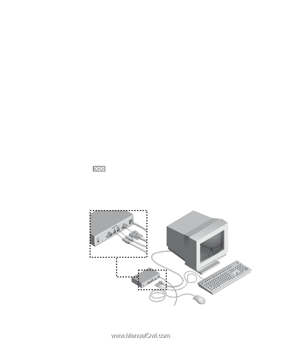
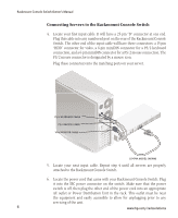
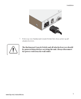
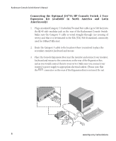
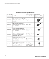
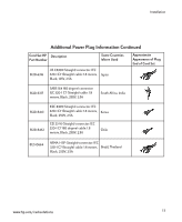
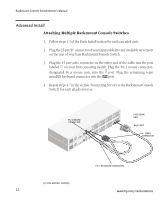
Rackmount Console Switch Owner's Manual Connecting the Optional J1475A HP Console Switch 2 User Expansion Kit (available in North America and Latin America only) 1. Plug a standard Category 5 Unshielded Twisted Pair cable (up to 500 feet) into the RJ-45 style modular jack on the rear of the Rackmount Console Switch. Make sure the Category 5 cable is wired straight through (no crossing of wires) and that it is terminated to the EIA (TIA) 568 B standard, commonly used for 10BaseT Ethernet. 2. Route the Category 5 cable to the location where you intend to place the secondary monitor, keyboard and mouse. 3. Place the Console Expansion Box near the monitor and connect your monitor, keyboard and mouse to the connectors on the rear of the Expansion Box just as you would connect them to your server. Make sure you connect your monitor's power supply to appropriate electrical outlets. (Please note that the connector on the rear of the Expansion Box is not used. Do not 8 www.hp.com/racksolutions
-
 1
1 -
2
-
3
-
4
-
5
-
6
-
7
-
8
-
 9
9 -
 10
10 -
 11
11 -
 12
12 -
 13
13 -
 14
14 -
 15
15 -
 16
16 -
 17
17 -
 18
18 -
 19
19 -
20
-
21
-
22
-
23
-
24
-
25
-
26
-
27
-
28
-
29
-
30
-
31
-
32
-
33
-
34
-
35
-
36
-
37
-
38
-
39
-
40
-
41
-
42
-
43
-
44
-
45
-
46
-
47
-
48
-
49
-
50
-
51
-
52
-
53
-
54
-
55
-
56
-
57
-
58
-
59
-
60
-
61
-
62
-
63
-
64
-
65
-
66
-
67
-
68
-
69
-
70
-
71
-
72
-
73
-
74
-
75
-
76
-
77
-
78
-
79
-
80
-
81
-
82
-
83
-
84
-
85
-
86
-
87
-
88
-
89
-
90
-
91
-
92
-
93
-
94
-
95
-
96
-
97
-
98
-
99
-
100
-
101
-
102
-
103
-
104
-
105
-
106
-
107
-
108
-
109
-
110
-
111
-
112
-
113
-
114
-
115
-
116
-
117
-
118
-
119
-
120
-
121
-
122
-
123
-
124
-
125
-
126
-
127
-
128
-
129
-
130
-
131
-
132
-
133
-
134
-
135
-
136
-
137
-
138
-
139
-
140
-
141
-
142
-
143
-
144
-
145
-
146
-
147
-
148
-
149
-
150
-
151
-
152
-
153
-
154
-
155
-
156
-
157
-
158
-
159
-
160
-
161
-
162
-
163
-
164
-
165
-
166
-
167
-
168
-
169
-
170
-
171
-
172
-
173
-
174
-
175
-
176
-
177
-
178
-
179
-
180
-
181
-
182
-
183
-
184
-
185
-
186
-
187
-
188
-
189
-
190
-
191
-
192
-
193
-
194
-
195
-
196
-
197
-
198
-
199
-
200
-
201
-
202
-
203
-
204
-
205
-
206
-
207
-
208
-
209
-
210
-
211
-
212
-
213
 |
 |