Compaq 6000 Maintenance & Service Guide: HP Compaq 6000 Pro Microtower Bus - Page 119
Front I/O Assembly, Preparation for Disassembly, on Access Panel, Front Bezel
 |
UPC - 894582579463
View all Compaq 6000 manuals
Add to My Manuals
Save this manual to your list of manuals |
Page 119 highlights
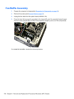
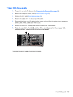
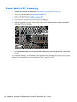
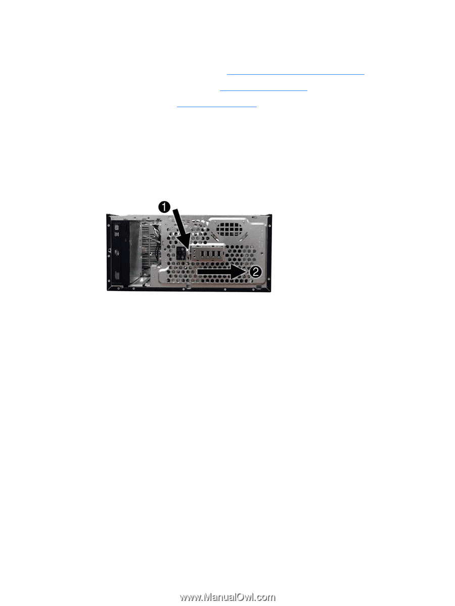
Front I/O Assembly 1. Prepare the computer for disassembly (Preparation for Disassembly on page 76). 2. Remove the computer access panel (Access Panel on page 77). 3. Remove the front bezel (Front Bezel on page 78). 4. Remove the cables from the clip on top of the baffle. 5. Disconnect the three front I/O cables (yellow, green, and blue) from the system board connectors (FRNT_USB1, FRNT_USB2, and FRNT_AUD). 6. Remove the silver T15 screw (1) that secures the assembly to the chassis. 7. Rotate the assembly to the right (2), and then lift the assembly away from the computer while threading the wires through the hole in the front of the chassis. To reinstall the panel, reverse the removal procedure. Front I/O Assembly 107
-
 1
1 -
2
-
3
-
4
-
5
-
6
-
7
-
8
-
9
-
10
-
11
-
12
-
13
-
14
-
15
-
16
-
17
-
18
-
19
-
20
-
21
-
22
-
23
-
24
-
25
-
26
-
27
-
28
-
29
-
30
-
31
-
32
-
33
-
34
-
35
-
36
-
37
-
38
-
39
-
40
-
41
-
42
-
43
-
44
-
45
-
46
-
47
-
48
-
49
-
50
-
51
-
52
-
53
-
54
-
55
-
56
-
57
-
58
-
59
-
60
-
61
-
62
-
63
-
64
-
65
-
66
-
67
-
68
-
69
-
70
-
71
-
72
-
73
-
74
-
75
-
76
-
77
-
78
-
79
-
80
-
81
-
82
-
83
-
84
-
85
-
86
-
87
-
88
-
89
-
90
-
91
-
92
-
93
-
94
-
95
-
96
-
97
-
98
-
99
-
100
-
101
-
102
-
103
-
104
-
105
-
106
-
107
-
108
-
109
-
110
-
111
-
112
-
113
-
 114
114 -
 115
115 -
 116
116 -
 117
117 -
 118
118 -
 119
119 -
 120
120 -
 121
121 -
 122
122 -
 123
123 -
 124
124 -
125
-
126
-
127
-
128
-
129
-
130
-
131
-
132
-
133
-
134
-
135
-
136
-
137
-
138
-
139
-
140
-
141
-
142
-
143
-
144
-
145
-
146
-
147
-
148
-
149
-
150
-
151
-
152
-
153
-
154
-
155
-
156
-
157
-
158
-
159
-
160
-
161
-
162
-
163
-
164
-
165
-
166
-
167
-
168
-
169
-
170
-
171
-
172
-
173
-
174
-
175
-
176
-
177
-
178
-
179
-
180
-
181
-
182
-
183
-
184
-
185
-
186
-
187
-
188
-
189
-
190
-
191
-
192
-
193
-
194
-
195
-
196
-
197
-
198
-
199
-
200
-
201
-
202
-
203
-
204
-
205
-
206
-
207
-
208
-
209
-
210
-
211
-
212
-
213
-
214
-
215
-
216
-
217
-
218
-
219
-
220
-
221
-
222
-
223
-
224
-
225
-
226
-
227
-
228
-
229
-
230
-
231
-
232
-
233
-
234
-
235
-
236
-
237
-
238
-
239
-
240
-
241
-
242
-
243
-
244
-
245
-
246
-
247
-
248
-
249
-
250
-
251
-
252
-
253
-
254
-
255
-
256
-
257
 |
 |
Front I/O Assembly
1.
Prepare the computer for disassembly (
Preparation for Disassembly
on page
76
).
2.
Remove the computer access panel (
Access Panel
on page
77
).
3.
Remove the front bezel (
Front Bezel
on page
78
).
4.
Remove the cables from the clip on top of the baffle.
5.
Disconnect the three front I/O cables (yellow, green, and blue) from the system board connectors
(FRNT_USB1, FRNT_USB2, and FRNT_AUD).
6.
Remove the silver T15 screw
(1)
that secures the assembly to the chassis.
7.
Rotate the assembly to the right
(2)
, and then lift the assembly away from the computer while
threading the wires through the hole in the front of the chassis.
To reinstall the panel, reverse the removal procedure.
Front I/O Assembly
107