Compaq 6000 Maintenance & Service Guide: HP Compaq 6000 Pro Microtower Bus - Page 132
Front Bezel Security
 |
UPC - 894582579463
View all Compaq 6000 manuals
Add to My Manuals
Save this manual to your list of manuals |
Page 132 highlights
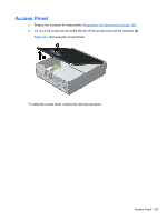
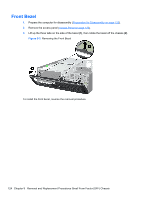
3. Screw the lock to the chassis using the screw provided. Figure 8-42 Attaching the Lock to the Chassis 4. Insert the plug end of the security cable into the lock (1) and push the button in (2) to engage the lock. Use the key provided to disengage the lock. Figure 8-43 Engaging the Lock Front Bezel Security The front bezel can be locked in place by installing a security screw provided by HP. To install the security screw: 1. Prepare the computer for disassembly (Preparation for Disassembly on page 76). 2. Remove the access panel (Access Panel on page 77). 3. Remove the front bezel (Front Bezel on page 78). 120 Chapter 8 Removal and Replacement Procedures Microtower (MT) Chassis
-
 1
1 -
2
-
3
-
4
-
5
-
6
-
7
-
8
-
9
-
10
-
11
-
12
-
13
-
14
-
15
-
16
-
17
-
18
-
19
-
20
-
21
-
22
-
23
-
24
-
25
-
26
-
27
-
28
-
29
-
30
-
31
-
32
-
33
-
34
-
35
-
36
-
37
-
38
-
39
-
40
-
41
-
42
-
43
-
44
-
45
-
46
-
47
-
48
-
49
-
50
-
51
-
52
-
53
-
54
-
55
-
56
-
57
-
58
-
59
-
60
-
61
-
62
-
63
-
64
-
65
-
66
-
67
-
68
-
69
-
70
-
71
-
72
-
73
-
74
-
75
-
76
-
77
-
78
-
79
-
80
-
81
-
82
-
83
-
84
-
85
-
86
-
87
-
88
-
89
-
90
-
91
-
92
-
93
-
94
-
95
-
96
-
97
-
98
-
99
-
100
-
101
-
102
-
103
-
104
-
105
-
106
-
107
-
108
-
109
-
110
-
111
-
112
-
113
-
114
-
115
-
116
-
117
-
118
-
119
-
120
-
121
-
122
-
123
-
124
-
125
-
126
-
 127
127 -
 128
128 -
 129
129 -
 130
130 -
 131
131 -
 132
132 -
 133
133 -
 134
134 -
 135
135 -
 136
136 -
 137
137 -
138
-
139
-
140
-
141
-
142
-
143
-
144
-
145
-
146
-
147
-
148
-
149
-
150
-
151
-
152
-
153
-
154
-
155
-
156
-
157
-
158
-
159
-
160
-
161
-
162
-
163
-
164
-
165
-
166
-
167
-
168
-
169
-
170
-
171
-
172
-
173
-
174
-
175
-
176
-
177
-
178
-
179
-
180
-
181
-
182
-
183
-
184
-
185
-
186
-
187
-
188
-
189
-
190
-
191
-
192
-
193
-
194
-
195
-
196
-
197
-
198
-
199
-
200
-
201
-
202
-
203
-
204
-
205
-
206
-
207
-
208
-
209
-
210
-
211
-
212
-
213
-
214
-
215
-
216
-
217
-
218
-
219
-
220
-
221
-
222
-
223
-
224
-
225
-
226
-
227
-
228
-
229
-
230
-
231
-
232
-
233
-
234
-
235
-
236
-
237
-
238
-
239
-
240
-
241
-
242
-
243
-
244
-
245
-
246
-
247
-
248
-
249
-
250
-
251
-
252
-
253
-
254
-
255
-
256
-
257
 |
 |
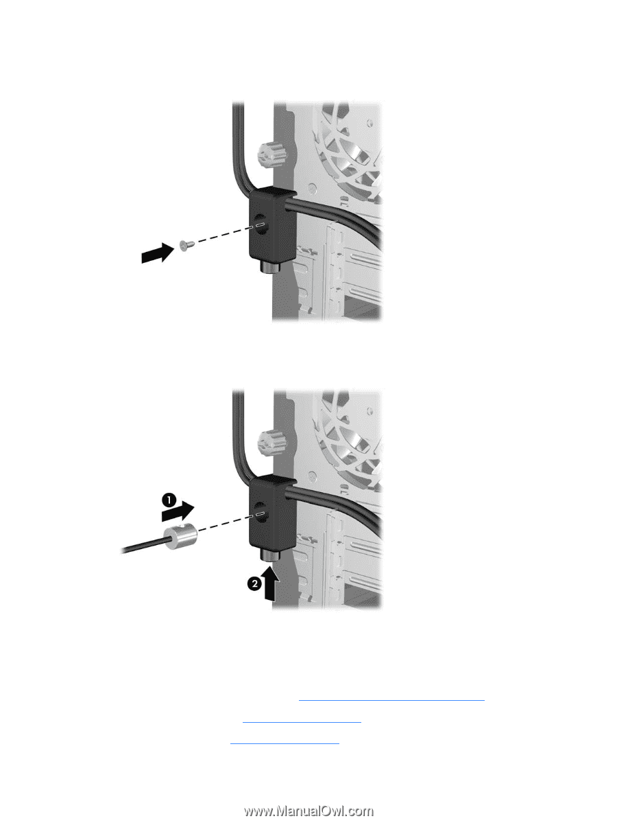
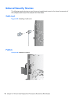
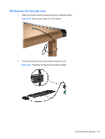
3.
Screw the lock to the chassis using the screw provided.
Figure 8-42
Attaching the Lock to the Chassis
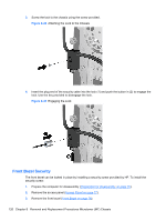
4.
Insert the plug end of the security cable into the lock (1) and push the button in (2) to engage the
lock. Use the key provided to disengage the lock.
Figure 8-43
Engaging the Lock
Front Bezel Security
The front bezel can be locked in place by installing a security screw provided by HP. To install the
security screw:
1.
Prepare the computer for disassembly (
Preparation for Disassembly
on page
76
).
2.
Remove the access panel (
Access Panel
on page
77
).
3.
Remove the front bezel (
Front Bezel
on page
78
).
120
Chapter 8
Removal and Replacement Procedures Microtower (MT) Chassis