Compaq 6000 Maintenance & Service Guide: HP Compaq 6000 Pro Microtower Bus - Page 140
Installing DIMMs, CAUTION,
 |
UPC - 894582579463
View all Compaq 6000 manuals
Add to My Manuals
Save this manual to your list of manuals |
Page 140 highlights
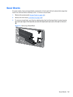
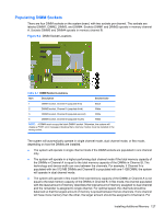
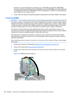
example, if you are populating the sockets with one 1-GB DIMM, and three 512-MB DIMMs, Channel A should be populated with the 1-GB DIMM and one 512-MB DIMM, and Channel B should be populated with the two 512-MB DIMMs. With this configuration, 2-GB will run as dual channel and 512-MB will run as single channel. ● In any mode, the maximum operational speed is determined by the slowest DIMM in the system. Installing DIMMs CAUTION: You must disconnect the power cord and wait approximately 30 seconds for the power to drain before adding or removing memory modules. Regardless of the power-on state, voltage is always supplied to the memory modules as long as the computer is plugged into an active AC outlet. Adding or removing memory modules while voltage is present may cause irreparable damage to the memory modules or system board. If you see an LED light on the system board, voltage is still present. The memory module sockets have gold-plated metal contacts. When upgrading the memory, it is important to use memory modules with gold-plated metal contacts to prevent corrosion and/or oxidation resulting from having incompatible metals in contact with each other. Static electricity can damage the electronic components of the computer or optional cards. Before beginning these procedures, ensure that you are discharged of static electricity by briefly touching a grounded metal object. When handling a memory module, be careful not to touch any of the contacts. Doing so may damage the module. 1. Prepare the computer for disassembly (Preparation for Disassembly on page 122). 2. Remove the access panel (Access Panel on page 123). 3. Rotate up the external drive bay housing to access the memory module sockets on the system board. Figure 9-5 Rotating the Drive Cage Up 128 Chapter 9 Removal and Replacement Procedures Small Form Factor (SFF) Chassis
-
 1
1 -
2
-
3
-
4
-
5
-
6
-
7
-
8
-
9
-
10
-
11
-
12
-
13
-
14
-
15
-
16
-
17
-
18
-
19
-
20
-
21
-
22
-
23
-
24
-
25
-
26
-
27
-
28
-
29
-
30
-
31
-
32
-
33
-
34
-
35
-
36
-
37
-
38
-
39
-
40
-
41
-
42
-
43
-
44
-
45
-
46
-
47
-
48
-
49
-
50
-
51
-
52
-
53
-
54
-
55
-
56
-
57
-
58
-
59
-
60
-
61
-
62
-
63
-
64
-
65
-
66
-
67
-
68
-
69
-
70
-
71
-
72
-
73
-
74
-
75
-
76
-
77
-
78
-
79
-
80
-
81
-
82
-
83
-
84
-
85
-
86
-
87
-
88
-
89
-
90
-
91
-
92
-
93
-
94
-
95
-
96
-
97
-
98
-
99
-
100
-
101
-
102
-
103
-
104
-
105
-
106
-
107
-
108
-
109
-
110
-
111
-
112
-
113
-
114
-
115
-
116
-
117
-
118
-
119
-
120
-
121
-
122
-
123
-
124
-
125
-
126
-
127
-
128
-
129
-
130
-
131
-
132
-
133
-
134
-
 135
135 -
 136
136 -
 137
137 -
 138
138 -
 139
139 -
 140
140 -
 141
141 -
 142
142 -
 143
143 -
 144
144 -
 145
145 -
146
-
147
-
148
-
149
-
150
-
151
-
152
-
153
-
154
-
155
-
156
-
157
-
158
-
159
-
160
-
161
-
162
-
163
-
164
-
165
-
166
-
167
-
168
-
169
-
170
-
171
-
172
-
173
-
174
-
175
-
176
-
177
-
178
-
179
-
180
-
181
-
182
-
183
-
184
-
185
-
186
-
187
-
188
-
189
-
190
-
191
-
192
-
193
-
194
-
195
-
196
-
197
-
198
-
199
-
200
-
201
-
202
-
203
-
204
-
205
-
206
-
207
-
208
-
209
-
210
-
211
-
212
-
213
-
214
-
215
-
216
-
217
-
218
-
219
-
220
-
221
-
222
-
223
-
224
-
225
-
226
-
227
-
228
-
229
-
230
-
231
-
232
-
233
-
234
-
235
-
236
-
237
-
238
-
239
-
240
-
241
-
242
-
243
-
244
-
245
-
246
-
247
-
248
-
249
-
250
-
251
-
252
-
253
-
254
-
255
-
256
-
257
 |
 |