Compaq 6000 Maintenance & Service Guide: HP Compaq 6000 Pro Microtower Bus - Page 159
Installing a Drive into the 3.5-inch External Drive Bay, CAUTION
 |
UPC - 894582579463
View all Compaq 6000 manuals
Add to My Manuals
Save this manual to your list of manuals |
Page 159 highlights
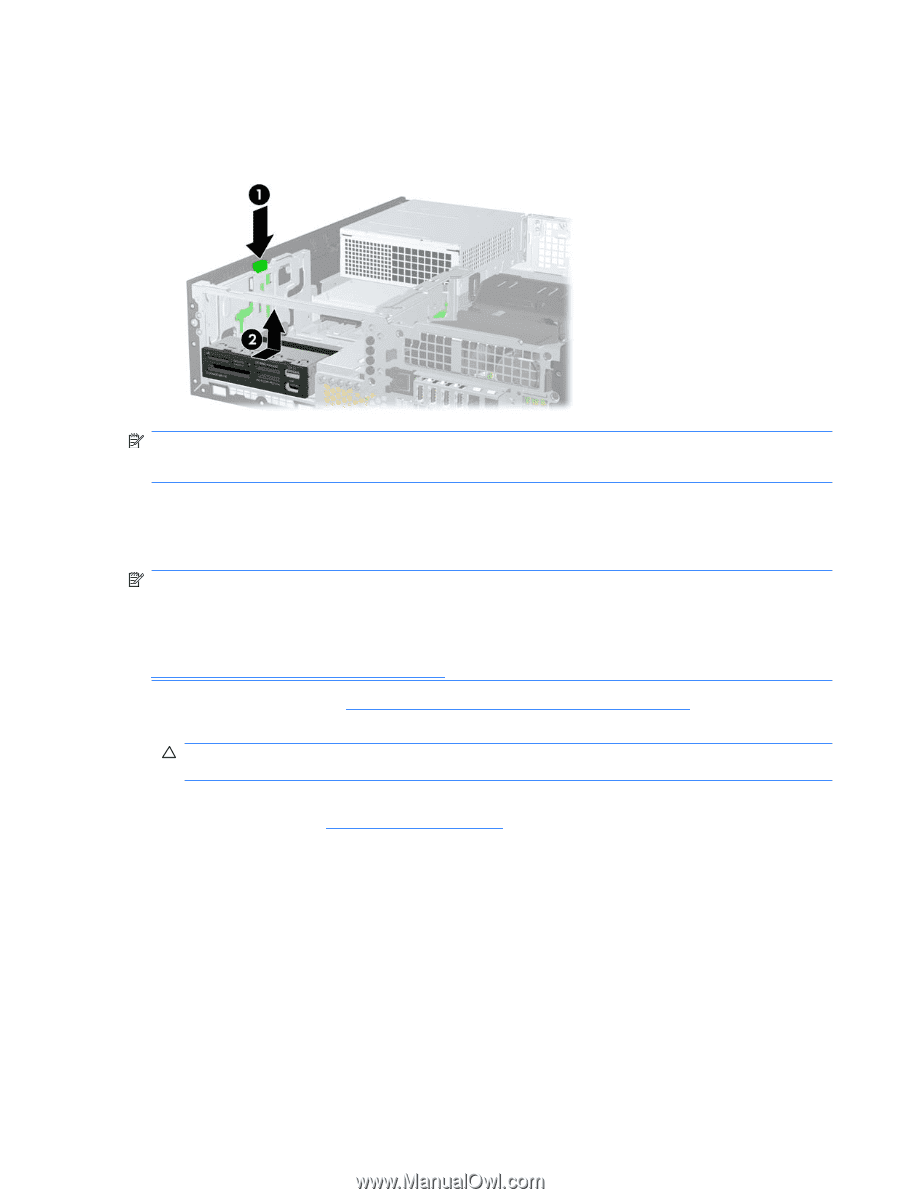
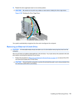
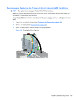
3. Press down on the green drive retainer button located on the left side of the drive to disengage the drive from the drive cage (1). While pressing the drive retainer button, slide the drive back until it stops, then lift it up and out of the drive cage (2). Figure 9-29 Removing a 3.5-inch Drive (Media Card Reader Shown) NOTE: To replace the 3.5-inch drive, reverse the removal procedure. When replacing a 3.5-inch drive, transfer the four guide screws from the old drive to the new one. Installing a Drive into the 3.5-inch External Drive Bay The 3.5-inch bay is located underneath the 5.25-inch drive. To install a drive into the 3.5-inch bay: NOTE: Install guide screws to ensure the drive will line up correctly in the drive cage and lock in place. HP has provided extra guide screws for the external drive bays (four 6-32 standard screws and four M3 metric screws), installed in the front of the chassis, under the front bezel. A secondary hard drive uses 6-32 standard screws. All other drives (except the primary hard drive) use M3 metric screws. The HPsupplied M3 metric screws are black and the HP-supplied 6-32 standard screws are silver. Refer to Installing and Removing Driveson page 138 for illustrations of the guide screw locations. 1. Follow the procedure in Removing an External 5.25-inch Drive on page 141 to remove the 5.25- inch drive and access the 3.5-inch drive bay. CAUTION: Ensure that the computer is turned off and that the power cord is disconnected from the electrical outlet before proceeding. 2. If you are installing a drive in a bay covered by a bezel blank, remove the front bezel then remove the bezel blank. See Bezel Blanks on page 125 for more information. Installing and Removing Drives 147
-
 1
1 -
2
-
3
-
4
-
5
-
6
-
7
-
8
-
9
-
10
-
11
-
12
-
13
-
14
-
15
-
16
-
17
-
18
-
19
-
20
-
21
-
22
-
23
-
24
-
25
-
26
-
27
-
28
-
29
-
30
-
31
-
32
-
33
-
34
-
35
-
36
-
37
-
38
-
39
-
40
-
41
-
42
-
43
-
44
-
45
-
46
-
47
-
48
-
49
-
50
-
51
-
52
-
53
-
54
-
55
-
56
-
57
-
58
-
59
-
60
-
61
-
62
-
63
-
64
-
65
-
66
-
67
-
68
-
69
-
70
-
71
-
72
-
73
-
74
-
75
-
76
-
77
-
78
-
79
-
80
-
81
-
82
-
83
-
84
-
85
-
86
-
87
-
88
-
89
-
90
-
91
-
92
-
93
-
94
-
95
-
96
-
97
-
98
-
99
-
100
-
101
-
102
-
103
-
104
-
105
-
106
-
107
-
108
-
109
-
110
-
111
-
112
-
113
-
114
-
115
-
116
-
117
-
118
-
119
-
120
-
121
-
122
-
123
-
124
-
125
-
126
-
127
-
128
-
129
-
130
-
131
-
132
-
133
-
134
-
135
-
136
-
137
-
138
-
139
-
140
-
141
-
142
-
143
-
144
-
145
-
146
-
147
-
148
-
149
-
150
-
151
-
152
-
153
-
 154
154 -
 155
155 -
 156
156 -
 157
157 -
 158
158 -
 159
159 -
 160
160 -
 161
161 -
 162
162 -
 163
163 -
 164
164 -
165
-
166
-
167
-
168
-
169
-
170
-
171
-
172
-
173
-
174
-
175
-
176
-
177
-
178
-
179
-
180
-
181
-
182
-
183
-
184
-
185
-
186
-
187
-
188
-
189
-
190
-
191
-
192
-
193
-
194
-
195
-
196
-
197
-
198
-
199
-
200
-
201
-
202
-
203
-
204
-
205
-
206
-
207
-
208
-
209
-
210
-
211
-
212
-
213
-
214
-
215
-
216
-
217
-
218
-
219
-
220
-
221
-
222
-
223
-
224
-
225
-
226
-
227
-
228
-
229
-
230
-
231
-
232
-
233
-
234
-
235
-
236
-
237
-
238
-
239
-
240
-
241
-
242
-
243
-
244
-
245
-
246
-
247
-
248
-
249
-
250
-
251
-
252
-
253
-
254
-
255
-
256
-
257
 |
 |