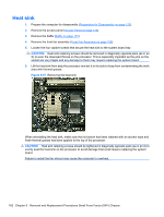
Compaq 6000 Maintenance & Service Guide: HP Compaq 6000 Pro Microtower Bus - Page 171
Front I/O and Power Switch Assembly,
 |
UPC - 894582579463
View all Compaq 6000 manuals
Add to My Manuals
Save this manual to your list of manuals |
Page 171 highlights
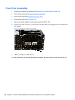
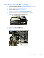
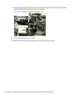
Front I/O and Power Switch Assembly 1. Prepare the computer for disassembly (Preparation for Disassembly on page 122). 2. Remove the access panel (Access Panel on page 123). 3. Remove the front bezel (Front Bezel on page 124). 4. Remove the front fan assembly (Front Fan Assembly on page 158). 5. Remove the black T15 screw (1) that secures the assembly to the chassis. Figure 9-47 Removing the front I/O device/power switch 6. Rotate the drive cage to its upright position. 7. Disconnect the cables (2) from the system board. Figure 9-48 Disconnecting the cables from the system board Front I/O and Power Switch Assembly 159
-
 1
1 -
2
-
3
-
4
-
5
-
6
-
7
-
8
-
9
-
10
-
11
-
12
-
13
-
14
-
15
-
16
-
17
-
18
-
19
-
20
-
21
-
22
-
23
-
24
-
25
-
26
-
27
-
28
-
29
-
30
-
31
-
32
-
33
-
34
-
35
-
36
-
37
-
38
-
39
-
40
-
41
-
42
-
43
-
44
-
45
-
46
-
47
-
48
-
49
-
50
-
51
-
52
-
53
-
54
-
55
-
56
-
57
-
58
-
59
-
60
-
61
-
62
-
63
-
64
-
65
-
66
-
67
-
68
-
69
-
70
-
71
-
72
-
73
-
74
-
75
-
76
-
77
-
78
-
79
-
80
-
81
-
82
-
83
-
84
-
85
-
86
-
87
-
88
-
89
-
90
-
91
-
92
-
93
-
94
-
95
-
96
-
97
-
98
-
99
-
100
-
101
-
102
-
103
-
104
-
105
-
106
-
107
-
108
-
109
-
110
-
111
-
112
-
113
-
114
-
115
-
116
-
117
-
118
-
119
-
120
-
121
-
122
-
123
-
124
-
125
-
126
-
127
-
128
-
129
-
130
-
131
-
132
-
133
-
134
-
135
-
136
-
137
-
138
-
139
-
140
-
141
-
142
-
143
-
144
-
145
-
146
-
147
-
148
-
149
-
150
-
151
-
152
-
153
-
154
-
155
-
156
-
157
-
158
-
159
-
160
-
161
-
162
-
163
-
164
-
165
-
 166
166 -
 167
167 -
 168
168 -
 169
169 -
 170
170 -
 171
171 -
 172
172 -
 173
173 -
 174
174 -
 175
175 -
 176
176 -
177
-
178
-
179
-
180
-
181
-
182
-
183
-
184
-
185
-
186
-
187
-
188
-
189
-
190
-
191
-
192
-
193
-
194
-
195
-
196
-
197
-
198
-
199
-
200
-
201
-
202
-
203
-
204
-
205
-
206
-
207
-
208
-
209
-
210
-
211
-
212
-
213
-
214
-
215
-
216
-
217
-
218
-
219
-
220
-
221
-
222
-
223
-
224
-
225
-
226
-
227
-
228
-
229
-
230
-
231
-
232
-
233
-
234
-
235
-
236
-
237
-
238
-
239
-
240
-
241
-
242
-
243
-
244
-
245
-
246
-
247
-
248
-
249
-
250
-
251
-
252
-
253
-
254
-
255
-
256
-
257
 |
 |
Front I/O and Power Switch Assembly
1.
Prepare the computer for disassembly (
Preparation for Disassembly
on page
122
).
2.
Remove the access panel (
Access Panel
on page
123
).
3.
Remove the front bezel (
Front Bezel
on page
124
).
4.
Remove the front fan assembly (
Front Fan Assembly
on page
158
).
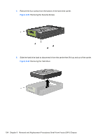
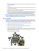
5.
Remove the black T15 screw
(1)
that secures the assembly to the chassis.
Figure 9-47
Removing the front I/O device/power switch
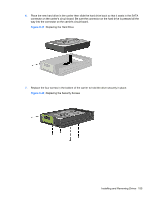
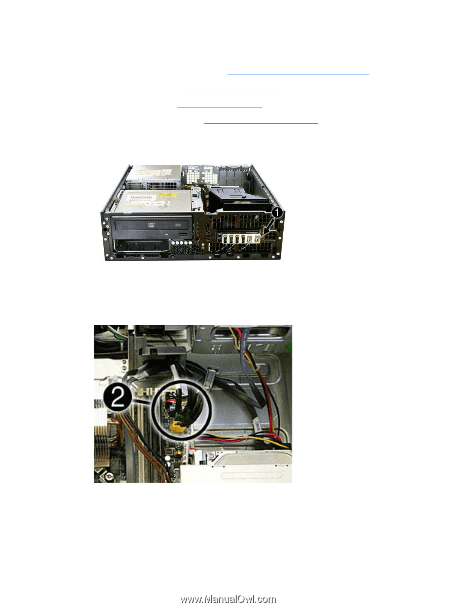
6.
Rotate the drive cage to its upright position.
7.
Disconnect the cables
(2)
from the system board.
Figure 9-48
Disconnecting the cables from the system board
Front I/O and Power Switch Assembly
159