Compaq Armada e500 Compaq Armada E500 and Armada V300 Maintenance and Service
Compaq Armada e500 - Notebook PC Manual
 |
View all Compaq Armada e500 manuals
Add to My Manuals
Save this manual to your list of manuals |
Compaq Armada e500 manual content summary:
- Compaq Armada e500 | Compaq Armada E500 and Armada V300 Maintenance and Service - Page 1
Compaq Armada E500, Armada E500S, and Armada V300 Series of Personal Computers Maintenance and Service Guide - Compaq Armada e500 | Compaq Armada E500 and Armada V300 Maintenance and Service - Page 2
warranty. MAINTENANCE AND SERVICE GUIDE Compaq Armada E500, E500S, and Armada V300 Series of Personal Computers Sixth Edition (October 2000) First Edition (November 1999) Published in the U.S.A., U.K., Singapore, and Taiwan. Documentation Part Number 128679-006 Spare Part Number 162812-001 - Compaq Armada e500 | Compaq Armada E500 and Armada V300 Maintenance and Service - Page 3
2.1 Preliminary Steps 2-2 2.2 Clearing Passwords 2-3 2.3 Power-On Self-Test (POST 2-4 2.4 POST Error Messages 2-4 2.5 Compaq Utilities 2-9 2.6 Troubleshooting Without Diagnostics 2-17 chapter3 ILLUSTRATED PARTS CATALOG 3.1 Serial Number Location 3-1 3.2 Computer System Major Components - Compaq Armada e500 | Compaq Armada E500 and Armada V300 Maintenance and Service - Page 4
5-8 5.8 Memory 5-12 5.9 Display Assembly 5-15 5.10 Real Time Clock (RTC) Battery 5-21 5.11 LED Board 5-22 5.12 Top Cover 5-23 5.13 Front Shield 5-27 5.14 Diskette Drive (Armada V300 only 5-29 5.15 System Board 5-30 5.16 Voltage Converter Board 5-34 5.17 Fan 5-36 chapter 6 SPECIFICATIONS - Compaq Armada e500 | Compaq Armada E500 and Armada V300 Maintenance and Service - Page 5
appendix A CONNECTOR PIN ASSIGNMENTS A-1 appendix B POWER CORD SET REQUIREMENTS 3-Conductor Power Cord Set B-1 Country-Specific Requirements B-2 Index ...I-1 Contents vii - Compaq Armada e500 | Compaq Armada E500 and Armada V300 Maintenance and Service - Page 6
GUIDE This Maintenance and Service Guide is a troubleshooting reference that can be used when servicing the Compaq Armada E500 and ArmadaV300 Series of Personal Computers. Compaq Computer Corporation reserves the right to make changes to the Compaq Armada E500 and Armada or specific instructions. - Compaq Armada e500 | Compaq Armada E500 and Armada V300 Maintenance and Service - Page 7
documentation set s Compaq Armada E500 and Armada V300 Series of Personal Computers Technical Reference Guide s Microsoft Operating System Manual s Compaq Service Training Guides s Compaq Service Advisories and Bulletins s Compaq QuickFind s Compaq Service Quick Reference Guide s Compaq Website at - Compaq Armada e500 | Compaq Armada E500 and Armada V300 Maintenance and Service - Page 8
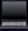
Port (AGP) implementation, and extensive multimedia support. The computers provide desktop functionality and connectivity through the optional expansion base, convenience base, or port replicator. Figure 1-1. Compaq Armada E500, E500S, and Armada V300 Personal Computers Product Description 1-1 - Compaq Armada e500 | Compaq Armada E500 and Armada V300 Maintenance and Service - Page 9
Compaq Armada E500 and E500S Model Naming Convention Key DVD-ROM drive drive 16 Integrated M = Mini PCI C = NIC/modem 0 = none communication V.90 modem combo 17-19RAM (in MB, 2-3 digits) 64 = 64 MB 20-21Operating system 98 = Windows 98 N4 = Windows NT 4.0 58 = Windows 95/98 dual install - Compaq Armada e500 | Compaq Armada E500 and Armada V300 Maintenance and Service - Page 10
Table 1-2 Compaq Armada E500 Computer Models 1 2 3 4 5-6 7-9 10 11 12 13-14 15 16 17-19 20-21 22 23 24 SKU# Config. Code A E 5 P3 Lithium Ion main battery pack 2 6-cell Lithium ion main battery pack 64 N2 179849-XX91 FWZ2 3 8X DVD-ROM drive 4 4X DVD-ROM drive Continued Product Description - Compaq Armada e500 | Compaq Armada E500 and Armada V300 Maintenance and Service - Page 11
22 23 24 SKU# Config. Code A E 5 P3 700 T 161609-XX11 DPB4 161609-XX31 DPB5 161609-XX61 DPB6 161609-XX71 DPB7 161609-XX81 FFD6 161609-XX91 FFD7 164764-XX11 DPB8 164764-XX61 DPB9 164764 battery pack 2 6-cell Lithium ion main battery DVD-ROM drive 4 4X DVD-ROM drive Continued 1-4 Product Description - Compaq Armada e500 | Compaq Armada E500 and Armada V300 Maintenance and Service - Page 12
continued 1 2 3 4 5-6 7-9 10 11 12 13-14 15 16 17-19 20-21 22 23 24 SKU# Config. Code A E 5 P3 600 T 3 X 6 D 0 A E 5 P3 600 T 3 X 6 D 0 A E 5 P3 600 C A E 5 P3 500 T 3 X 6 D C 1 9-cell Lithium Ion main battery pack 64 58 179844-XX11 FL51 64 N2 179844-XX81 FL53 64 58 179845-XX11 FL54 64 N2 - Compaq Armada e500 | Compaq Armada E500 and Armada V300 Maintenance and Service - Page 13
Table 1-2 continued 1 2 3 4 5-6 7-9 10 11 12 13-14 15 16 17-19 20-21 22 23 24 SKU# Config. Code A E 5 P3 500 T 2 S 6 D 0 64 A E 5 P3 500 T 2 S 6 D 0 64 A E 5 P3 500 T 2 S 6 D 0 64 A E 5 P3 500 T 2 S 6 D M 64 battery pack 2 6-cell Lithium ion main battery pack Continued 1-6 Product Description - Compaq Armada e500 | Compaq Armada E500 and Armada V300 Maintenance and Service - Page 14
continued 1 2 3 4 5-6 7-9 10 11 12 13-14 15 16 17-19 20-21 22 23 24 SKU# Config. Code A E 5 P2 366 T 2 S 4 D 0 A E 5 P2 366 T 2 S 4 D 0 A E 5 P2 366 C A E 5 C1 600 T 3 X 5 D C 1 9-cell Lithium Ion main battery pack 64 58 155058-XX11 DJC1 64 98 155058-XX41 DJC2 64 N4 155058-XX61 DJC3 64 58 - Compaq Armada e500 | Compaq Armada E500 and Armada V300 Maintenance and Service - Page 15
Table 1-2 continued 1 2 3 4 5-6 7-9 10 11 12 13-14 15 16 17-19 20-21 22 23 24 SKU# Config. Code A E 5 C1 550 T 4 X 6 D C 64 58 A E 5 C1 550 T 4 X 6 D C 64 N2 207057-XX12 FVX1 207057-XX82 FVX2 A E 5 C1 550 T 3 X 5 D 0 64 58 A E 5 9-cell Lithium Ion main battery pack 2 6-cell Lithium ion main - Compaq Armada e500 | Compaq Armada E500 and Armada V300 Maintenance and Service - Page 16
naming conventions are shown in Table 1-3. The computer model designation is composed of a group of characters that define each model's features. Table 1-3 Compaq Armada V300 Model Naming Convention Key A V 3 C1 500 T4X 6 D M 64 58 N S F 1 2 3 4 5-6 7-9 10-12 13-14 15 16 17-19 20-21 22 23 24 - Compaq Armada e500 | Compaq Armada E500 and Armada V300 Maintenance and Service - Page 17
Table 1-4 Compaq Armada V300 Computer Models 1 2 3 4 5-6 7-9 10 11 12 13-14 15 16 17-19 20-21 22 23 24 SKU# Config. Code A V 3 C1 500 T 4 X 6 D 0 58 A V 3 C1 466 H 3 S 6 D C N4 1 9-cell Lithium Ion main battery pack 2 6-cell Lithium ion main battery pack 64 P 64 P 64 P 64 N P 64 P 64 N P 64 P 64 - Compaq Armada e500 | Compaq Armada E500 and Armada V300 Maintenance and Service - Page 18
Table 1-4 continued 1 2 3 4 5-6 7-9 10 11 12 13-14 15 16 17-19 20-21 22 23 24 SKU# Config. Code A V 3 C1 466 T 2 S 6 D 0 58 64 P 163305-XX22 DVQ1 A V 3 C1 466 T 2 S 6 D 0 N4 64 P 163305-XX62 DVQ3 A V 3 C1 466 main battery pack 2 6-cell Lithium ion main battery pack Product Description 1-11 - Compaq Armada e500 | Compaq Armada E500 and Armada V300 Maintenance and Service - Page 19
graphics) s The following standard memory is available, varying by computer model: s The Armada E500 and E500S are equipped with 64-MB highperformance varying by computer model: s The Armada E500 and E500S support a TouchPad or pointing stick keyboard. s The Armada V300 is equipped with a TouchPad - Compaq Armada e500 | Compaq Armada E500 and Armada V300 Maintenance and Service - Page 20
at one time. s The Armada V300 supports a 9- or 6-cell Li ion primary battery pack in the battery bay and a 6-cell Li ion MultiBay battery pack in the MultiBay. s The following hard drives are available, varying by computer model: s The Armada E500 and E500S support 18.0-, 12.0-, 6.0-, or 4.3GB - Compaq Armada e500 | Compaq Armada E500 and Armada V300 Maintenance and Service - Page 21
hardware problems. s Security Management-prevents unauthorized access to data and components. s Configuration Management-optimizes the computer by providing the latest drivers, utilities, and software, which are available on CD-ROM and the Compaq Web site at: www.compaq.com/support/portables - Compaq Armada e500 | Compaq Armada E500 and Armada V300 Maintenance and Service - Page 22
Compaq computers, monitors, hard drives, battery packs, memory boards, processor speeds, and operating systems s System board and ROM revision levels s BIOS the following alerts: s Hard drive alert-provides 72-hour advance warning of impending hard drive problems and can automatically start optional - Compaq Armada e500 | Compaq Armada E500 and Armada V300 Maintenance and Service - Page 23
A battery charging problem alert is reported only on the computer display. s When the computer is not connected to a network, the user receives Power-On and Setup Passwords-prevent unauthorized access to information and computer configuration. s DriveLock-prevents unauthorized access to hard drives - Compaq Armada e500 | Compaq Armada E500 and Armada V300 Maintenance and Service - Page 24
Web site at: www.compaq.com/support/portables Managing Power The computer comes with a collection of power management features that allow battery operating time to be extended and power to be conserved. Use power management to monitor most computer components such as the hard drive, processor, and - Compaq Armada e500 | Compaq Armada E500 and Armada V300 Maintenance and Service - Page 25
1.3 Computer External Components The external components on the display and left side of the computer are shown in Figure 1-2 and described in Table 1-5. Figure 1-2. Display and Left Side Components 1-18 Product Description - Compaq Armada e500 | Compaq Armada E500 and Armada V300 Maintenance and Service - Page 26
the following MultiBay devices: CD-ROM drive, CD-RW drive, DVD-ROM drive, hard drive (in Hard Drive MultiBay Adapter), SuperDisk LS-120 Drive, 6-cell Li ion MultiBay battery pack. 7 Volume buttons Adjust the volume of the stereo speakers. 8 Power/suspend light On-power is turned on. (green) Off - Compaq Armada e500 | Compaq Armada E500 and Armada V300 Maintenance and Service - Page 27
The external components on the right side of the computer are shown in Figure 1-3 and are described in Table 1-6. Figure 1-3. Right Side Components 1-20 Product Description - Compaq Armada e500 | Compaq Armada E500 and Armada V300 Maintenance and Service - Page 28
Right Side Components Item Component Function 1 PC Card slots* Supports 32-bit (CardBus) and 16-bit PC Cards. 2 Stereo a television, VCR, camcorder, or overhead projector. * The Armada E500 and E500S have two PC Card slots; the Armada V300 has only one PC Card slot. Product Description 1-21 - Compaq Armada e500 | Compaq Armada E500 and Armada V300 Maintenance and Service - Page 29
The external components on the rear of the computer are shown in Figure 1-4 and described in Table 1-7. Figure 1-4. Rear Components 1-22 Product Description - Compaq Armada e500 | Compaq Armada E500 and Armada V300 Maintenance and Service - Page 30
(USB) connector for video conferencing, or hubs which connect multiple USB devices. The USB connector is a powered hub. When running Windows 95 or higher or Windows NT, any combination of up to five powered or unpowered hubs can be connected in any sequence, as long as two unpowered hubs are not - Compaq Armada e500 | Compaq Armada E500 and Armada V300 Maintenance and Service - Page 31
Computer keyboard components are shown in Figure 1-5 and described in Table 1-8. Figure 1-5. Keyboard Components 1-24 Product Description - Compaq Armada e500 | Compaq Armada E500 and Armada V300 Maintenance and Service - Page 32
Compaq Armada user information for quick answers to your computer questions. This key is present only on computer models with config. codes application. This key is present only on computer models with config. codes beginning with "FL5," "FL6," "FM," "FV," and "FW." 5 Power switch Turns the - Compaq Armada e500 | Compaq Armada E500 and Armada V300 Maintenance and Service - Page 33
Additional computer keyboard components are shown in Figure 1-6 and described in Table 1-9. Figure 1-6. Keyboard Components (continued) 1-26 Product Description - Compaq Armada e500 | Compaq Armada E500 and Armada V300 Maintenance and Service - Page 34
Table 1-9 Keyboard Components (continued) Item Component Function 1 Hard drive light (green) Turns on when the hard drive is being accessed. 2 MultiBay light (green) Turns on when a MultiBay device is being accessed or a battery pack in the MultiBay is charging or waiting to be charged. 3 Num - Compaq Armada e500 | Compaq Armada E500 and Armada V300 Maintenance and Service - Page 35
from the battery bay. 3 Hard drive cover release latch Releases the hard drive cover. 4 Hard drive cover screw Secures the hard drive cover. 5 Hard drive cover Covers the hard drive bay. 6 Diskette drive release Releases the device from the DualBay on latch the Armada E500. Releases the - Compaq Armada e500 | Compaq Armada E500 and Armada V300 Maintenance and Service - Page 36
provides the following device connections: s Memory expansion board s Hard drive s Display s Keyboard/TouchPad or pointing stick s Audio s Intel Pentium III, II, or Celeron processors s Fan s PC Cards s Modem or modem/NIC The Armada E500, E500S, and Armada V300 computers use an electrical fan for - Compaq Armada e500 | Compaq Armada E500 and Armada V300 Maintenance and Service - Page 37
order in which they are given. s Repeat POST after each recommended action until the problem is resolved and the error message does not return. s When the problem is resolved, stop performing the troubleshooting steps and do not complete the remaining recommended actions. s Refer to Chapter 5 for - Compaq Armada e500 | Compaq Armada E500 and Armada V300 Maintenance and Service - Page 38
and interrupt the test. Before running POST, complete the following steps: 1. Obtain established passwords. If you must clear the passwords, go to Section 2.2. 2. Ensure that the battery pack is installed in the computer and the power cord is connected to the computer and plugged into an AC - Compaq Armada e500 | Compaq Armada E500 and Armada V300 Maintenance and Service - Page 39
the problem by running POST with and without the external device connected. 8. Use Compaq Utilities and loopback plugs in the serial and parallel connectors if you plan to test these ports. Follow these steps to run Compaq Utilities: a. If you are running Compaq Utilities from the hard drive, turn - Compaq Armada e500 | Compaq Armada E500 and Armada V300 Maintenance and Service - Page 40
boots from the hard drive or from a bootable diskette if one is installed in the diskette drive. 2.4 POST Error Messages If the system is not functioning well enough to run POST, or if the display is not functioning well enough to show POST error messages, refer to the Troubleshooting tables - Compaq Armada e500 | Compaq Armada E500 and Armada V300 Maintenance and Service - Page 41
controller error The hard drive Check the drive parameters. controller failed Turn off the system and to respond to the check all related reset command. connections. Keyboard controller failure The keyboard failed the selftest command. Replace the system board. Continued Troubleshooting 2-5 - Compaq Armada e500 | Compaq Armada E500 and Armada V300 Maintenance and Service - Page 42
persists, (RTC) have been replace RTC battery. corrupted, possibly by a 3. If problems persists, power loss. replace system board. Hard disk xx failure (or A failure or an error) error occurred when trying to access the hard drive. 1. Run ScanDisk. 2. Check disk in DOS and Windows - Compaq Armada e500 | Compaq Armada E500 and Armada V300 Maintenance and Service - Page 43
read/write 5 of various Interrupt Controller registers failed. ROM checksum incorrect A checksum of the ROM 2 BIOS does not match the byte value at F000:FFFF. RAM error at location xxxx RAM error occurred during memory test. None *Beep codes are defined in Table 2-3. Troubleshooting 2-7 - Compaq Armada e500 | Compaq Armada E500 and Armada V300 Maintenance and Service - Page 44
failed. 6 S-S-S-P-L-L-L-P The keyboard controller failed. 7 S-S-L-P-S-S-S-P Graphics adapter is faulty. 8 S-S-L-P-S-S-L-P Internal RAM is Replace memory faulty. board or system board if memory on system board is faulty. NOTE: S = Short, L = Long, P = Pause 2-8 Troubleshooting - Compaq Armada e500 | Compaq Armada E500 and Armada V300 Maintenance and Service - Page 45
corner of the display. 3. Select a menu option. Selecting Computer Setup or Compaq Diagnostics for Windows The computer features two system and remove programs, and provide Wizards to ensure proper device drivers are installed. Compaq Diagnostics for Windows is NOT a configuration tool and might only - Compaq Armada e500 | Compaq Armada E500 and Armada V300 Maintenance and Service - Page 46
Setup, press Esc. 2. Select the File, Security, or Advanced menu. 3. To close Computer Setup and restart the computer: s Select File!Ignore Changes and Exit, then press Enter. or s Select File!Save Changes and Exit, then press Enter. 4. To confirm your choice, press F10. 2-10 Troubleshooting - Compaq Armada e500 | Compaq Armada E500 and Armada V300 Maintenance and Service - Page 47
Menu Begin here System information Save to floppy Restore from floppy Restore defaults Ignore changes and exit Save changes and exit To do this s View identification information about the computer, docking base, and battery packs s View specification information about the processor, memory and - Compaq Armada e500 | Compaq Armada E500 and Armada V300 Maintenance and Service - Page 48
Enter, change, or delete a DriveLock password Enable/disable: s Ports or diskette drives s Diskette write s CD-ROM or diskette startup (Settings for a DVD-ROM can be entered in the CD-ROM field.) Enter identification numbers for the computer, a docking base, and battery packs 2-12 Troubleshooting - Compaq Armada e500 | Compaq Armada E500 and Armada V300 Maintenance and Service - Page 49
by eliminating some startup tests (If you suspect a memory failure and want to test memory automatically during startup, you may want to disable QuickBoot.) s MultiBoot, which enables you to set a startup sequence that can include any drives in the system s Enable/disable the embedded numeric - Compaq Armada e500 | Compaq Armada E500 and Armada V300 Maintenance and Service - Page 50
selecting Start!Settings!Control Panel!Compaq Diagnostics. 2. To select a category, choose one of two methods: s Select the Categories menu, then select a category or save it to a drive, select the File menu, then select Print or Save As. 5. To exit, select File menu!Exit. 2-14 Troubleshooting - Compaq Armada e500 | Compaq Armada E500 and Armada V300 Maintenance and Service - Page 51
Hard drive boot sequence 1 Hard drive in the computer MultiBay 2 Hard drive in the computer hard drive bay Boot display Auto Language Language of country Table 2-5 Ports Serial port 3F8, IRQ4 Infrared port 2F8, IRQ9 Parallel port 378, IRQ7 Ethernet port 300, IRQ11 Troubleshooting - Compaq Armada e500 | Compaq Armada E500 and Armada V300 Maintenance and Service - Page 52
to be customized. Default settings are: Suspend Time: disabled Hibernation Timeout: low battery Drive Timeout: always on Screen Timeout: always on Table 2-7 Security Enable QuickLock/QuickBlank Enable Power-on Password Disable Serial/Infrared Ports Disable Parallel Port Disable PC Card Slots Setup - Compaq Armada e500 | Compaq Armada E500 and Armada V300 Maintenance and Service - Page 53
Parts When troubleshooting a problem, check the following items for possible solutions before replacing parts: s Verify that cables are connected properly to the suspected defective parts. s Verify that all required device drivers are installed. s Verify that all printer drivers have been installed - Compaq Armada e500 | Compaq Armada E500 and Armada V300 Maintenance and Service - Page 54
Table 2-8 Solving Audio Problems Problem Possible Cause Solution Computer does not System beeps have Use the Fn+F5 hotkeys to beep after the Power- been turned down. turn up the system On Self-Test (POST). volume. Internal speaker does Volume may be not produce sound turned off or set - Compaq Armada e500 | Compaq Armada E500 and Armada V300 Maintenance and Service - Page 55
Table 2-8 continued Problem Possible Cause Solution External microphone does not work (continued). Sound source is not selected. Ensure that microphone is the Fn+F5 hotkeys. s Check the mixing features available by double-clicking the Speaker icon on the Windows taskbar. Troubleshooting 2-19 - Compaq Armada e500 | Compaq Armada E500 and Armada V300 Maintenance and Service - Page 56
Table 2-9 Solving Battery/Battery Gauge Problems Problem Possible Cause Solution Computer is beeping Battery pack charge and battery power is low. light is blinking. s Charge the battery pack by connecting it to an external power source. s Replace the battery pack with another fully charged - Compaq Armada e500 | Compaq Armada E500 and Armada V300 Maintenance and Service - Page 57
5.10). Battery gauge seems The battery pack inaccurate. needs calibration. Recalibrate the battery. The battery pack has Replace the battery pack. reached the end of its useful life. Battery pack is warm Warming occurs after charging. during charging. No action is required. Troubleshooting - Compaq Armada e500 | Compaq Armada E500 and Armada V300 Maintenance and Service - Page 58
has a scratch Insert a different disc. on its surface. CD-ROM drive or DVD-ROM drive is not detected by the computer. Drive is not connected properly. If you are running a version of Windows that was preinstalled by Compaq, remove the drive from the MultiBay and reinsert it. If you are running - Compaq Armada e500 | Compaq Armada E500 and Armada V300 Maintenance and Service - Page 59
up from diskette or SuperDisk LS-120 drive. A bootable diskette is Verify that a diskette with not in the drive. the necessary system files is in the drive. Diskette bootability is Enable diskette disabled in Computer bootability in Computer Setup. Setup!Security menu. Troubleshooting 2-23 - Compaq Armada e500 | Compaq Armada E500 and Armada V300 Maintenance and Service - Page 60
Table 2-12 Solving Hard Drive Problems Problem Possible Cause Solution Accessing information on the hard drive is much slower than usual. Hard drive entered low power state due to timeout and is now exiting from it. Wait for the system to restore the previously saved data prior to initiating a - Compaq Armada e500 | Compaq Armada E500 and Armada V300 Maintenance and Service - Page 61
does not have an IrDA-compliant infrared port. Your Compaq computer uses the IrDA communications protocol. Communication between infrared devices must use the same communications protocol. Check the manufacturer's instructions for connecting with infrared devices or try connecting with a device - Compaq Armada e500 | Compaq Armada E500 and Armada V300 Maintenance and Service - Page 62
Problem Cannot transmit data Infrared port doesn't work. Possible Cause Direct sunlight, fluorescent light, or flashing incandescent light is close to the infrared connections. There is interference from other wireless other wireless devices wireless headphones units such as wireless headphones and other - Compaq Armada e500 | Compaq Armada E500 and Armada V300 Maintenance and Service - Page 63
Problems Problem Possible Cause Solution Screen is blank and keyboard is working. A screen timeout has Press any key to refresh been initiated. the screen. QuickLock/QuickBlank has been initiated. To enable the keyboard and return your information to the screen, enter your power-on password - Compaq Armada e500 | Compaq Armada E500 and Armada V300 Maintenance and Service - Page 64
Modem Problems location has call waiting. Select *70, 70#, or 1170 from the drop-down list to disable call waiting. Try connecting at a later time. Check the computer BIOS setup. If it requires specific settings for modems, be sure that they have been enabled. Continued 2-28 Troubleshooting - Compaq Armada e500 | Compaq Armada E500 and Armada V300 Maintenance and Service - Page 65
Table 2-15 continued Problem Possible Cause Solution Modem does not dial correctly. Telephone number is not entered correctly in the modem's dialing loose, they can cause noise on the line. s Check with your local telephone company for a phone line filter. Continued Troubleshooting 2-29 - Compaq Armada e500 | Compaq Armada E500 and Armada V300 Maintenance and Service - Page 66
Table 2-15 continued Problem Phone line noise is causing a disconnection. No dial tone Possible Cause Solution Hang-up Delay S Register (S10) is set too low. Phone service is not connected to the telephone wall contact your local phone company or building manager. Continued 2-30 Troubleshooting - Compaq Armada e500 | Compaq Armada E500 and Armada V300 Maintenance and Service - Page 67
then go to Terminal Mode. 2. Type AT and press the Enter key. If the modem displays OK, the modem and computer are working together support the highest connect speeds. Have your telephone line checked by your local telephone service provider. Try dialing an alternate telephone number for the service - Compaq Armada e500 | Compaq Armada E500 and Armada V300 Maintenance and Service - Page 68
). Possible Cause Solution The service or site called does not support 56K or supports an incompatible 56K implementation. An internal modem supports K56flex. To find an Internet service provider (ISP) that supports K56flex, go to the Compaq Web site at: www.compaq.com There is noise on - Compaq Armada e500 | Compaq Armada E500 and Armada V300 Maintenance and Service - Page 69
of PC driver is not PCMCIA Cards tested successfully compliant. in Compaq PC Card instructions for formatting a hard drive card or installing PC Card-specific drivers for a network card. Network PC Card does not work. Necessary drivers are not installed (turned on). Refer to the instructions - Compaq Armada e500 | Compaq Armada E500 and Armada V300 Maintenance and Service - Page 70
Table 2-16 continued Problem Network PC Card does not work (continued). Storage PC Card does not work. Possible Cause Solution Network PC Card or Check the list of PC driver is not PCMCIA Cards tested successfully compliant. in Compaq PC Card platforms. SRAM and flash memory PC Cards require - Compaq Armada e500 | Compaq Armada E500 and Armada V300 Maintenance and Service - Page 71
Table 2-17 Solving Power Problems Problem Possible Cause Solution Computer will not turn on. Battery is discharged and computer is not connected to a power source. s Charge the battery pack. s Replace the battery pack. s Connect the computer to an external power source. Battery is discharged - Compaq Armada e500 | Compaq Armada E500 and Armada V300 Maintenance and Service - Page 72
or screen blanking utility installed. Press any key to refresh the screen. Screen timeout was Press any key to light the initiated. screen. System initiated Press the suspend button Suspend after a to exit Suspend. user-defined timeout expired. Computer initiated a low battery Suspend or - Compaq Armada e500 | Compaq Armada E500 and Armada V300 Maintenance and Service - Page 73
Table 2-18 continued Problem Possible Cause Solution Characters on computer display are dim (continued). Power Management, which controls Suspend and Hibernation, is disabled and the battery pack has discharged. s Replace the battery pack and turn on the computer. s Connect the computer to an - Compaq Armada e500 | Compaq Armada E500 and Armada V300 Maintenance and Service - Page 74
2-19 Solving USB Problems Problem Possible Cause Solution during startup (before Windows 95 loads). During startup, only two tiers are supported by the USB port. These tiers can include no more than two hubs on Use only powered hubs. Make sure that all unpowered hubs are immediately preceded by - Compaq Armada e500 | Compaq Armada E500 and Armada V300 Maintenance and Service - Page 75
CATALOG This chapter provides an illustrated parts breakdown and a reference for spare part numbers and option part numbers for the Compaq Armada E500, E500S, and Armada V300 Series of Personal Computers. 3.1 Serial Number Location When ordering parts or requesting information, provide the computer - Compaq Armada e500 | Compaq Armada E500 and Armada V300 Maintenance and Service - Page 76
3.2 Computer System Major Components Figure 3-2. Computer System Major Components 3-2 Illustrated Parts Catalog - Compaq Armada e500 | Compaq Armada E500 and Armada V300 Maintenance and Service - Page 77
System Major Components Item Description Spare Part Number 1 Display assembly 15.0-inch, TFT, SXGA (Armada E500 and E500S only); used only with config. codes beginning with JFC. 201059-001 15.0-inch, TFT, XGA (Armada E500 and E500S only); used only with config. codes beginning with DX and FFH - Compaq Armada e500 | Compaq Armada E500 and Armada V300 Maintenance and Service - Page 78
Computer System Major Components (continued) 3-4 Illustrated Parts Catalog - Compaq Armada e500 | Compaq Armada E500 and Armada V300 Maintenance and Service - Page 79
Spare Part Number 3 LED board used with all config. codes except those 159539-001 beginning with FL5, FL6, FM, FV, FW, and JF. used with all config. codes beginning with 201058-001 FL5, FL6, FM, FV, FW, and JF. 4 Keyboard with pointing stick 154876-XXX (Armada E500 and E500S only - Compaq Armada e500 | Compaq Armada E500 and Armada V300 Maintenance and Service - Page 80
Computer System Major Components (continued) 3-6 Illustrated Parts Catalog - Compaq Armada e500 | Compaq Armada E500 and Armada V300 Maintenance and Service - Page 81
Item Description Spare Part Number 7 System board Armada E500 and E500S only (all with 64 MB SDRAM) Intel Pentium III 850-MHz processor; used 217374-001 only with config. codes beginning with JFC. Intel Pentium III 800-MHz processor; used 217373-001 only with config. codes beginning with JFB - Compaq Armada e500 | Compaq Armada E500 and Armada V300 Maintenance and Service - Page 82
Computer System Major Components (continued) 3-8 Illustrated Parts Catalog - Compaq Armada e500 | Compaq Armada E500 and Armada V300 Maintenance and Service - Page 83
Spare Part Number 7 System board (continued) Armada V300 only Intel Celeron 500-MHz processor with 64 MB SDRAM; used only with config. codes beginning with DVR. Intel Celeron 466-MHz processor with 64 MB SDRAM; used only with config. codes beginning with DVP. 177748-001 177747-001 Intel - Compaq Armada e500 | Compaq Armada E500 and Armada V300 Maintenance and Service - Page 84
Computer System Major Components (continued) 3-10 Illustrated Parts Catalog - Compaq Armada e500 | Compaq Armada E500 and Armada V300 Maintenance and Service - Page 85
battery pack, 6 cell (also available as an 159529-001 option) 10 CPU base enclosure 159534-001 11a Removable diskette drive (Armada E500 and 159538-001 11b E500S only) Fixed diskette drive (Armada V300 only) 160537-001 12 Removable hard drive 20.0 GB (Armada E500 and E500S only) 218371-001 - Compaq Armada e500 | Compaq Armada E500 and Armada V300 Maintenance and Service - Page 86
FM, FV, and FW. 1b includes Easy Access buttons; used with config. codes beginning with FL5, FL6, FM, FV, FW, and JF. 2 Hinge cover 3 Real time clock (RTC) battery 4 Front shield 5 Diskette drive bezel 6 Diskette drive space saver 7 Hard drive cover 8 Mini PCI slot cover 9 CD-ROM - Compaq Armada e500 | Compaq Armada E500 and Armada V300 Maintenance and Service - Page 87
drive 3 8X DVD-ROM drive 4X DVD-ROM drive 4 Removable diskette drive, 1.44-megabyte, 3.5-inch (standard on Armada E500 and E500S only) 5 LS-120 SuperDisk drive (available only as an option) 6 Fixed diskette drive (Armada V300 only) Spare Part Number 218371-001 167528-001 167527-001 218370-001 - Compaq Armada e500 | Compaq Armada E500 and Armada V300 Maintenance and Service - Page 88
Armada E500, E500S, and Armada V300 Maintenance 162812-001 & Service Guide Battery charger 153991-001 Hard drive adapter 155352-001 Memory expansion board 256 MB 128 MB 64 MB 32 MB 167136-001 135244-001 135243-001 135242-001 Miscellaneous Screw Kit 159537-001 Return Kit 159541-001 Power - Compaq Armada e500 | Compaq Armada E500 and Armada V300 Maintenance and Service - Page 89
T-8 screwdriver s Phillips screwdriver (for screw securing diskette drive bezel to base assembly on Armada V300 only) s 7-mm hex socket (for bushing guides) s Tool kit (includes connector removal tool, loopback plugs, and case utility tool) 4.2 Service Considerations Listed below are some of the - Compaq Armada e500 | Compaq Armada E500 and Armada V300 Maintenance and Service - Page 90
parts being removed or replaced. Handle flex cables with extreme care; they tear easily. CAUTION: When servicing the computer, ensure that cables are placed in their proper location removable drive, or loss of information, observe these precautions: s Before removing or inserting a hard drive, shut - Compaq Armada e500 | Compaq Armada E500 and Armada V300 Maintenance and Service - Page 91
drive into a drive bay. s After inserting a hard drive into the hard drive bay, always reinsert either the original hard drive security plate or the tamper-resistant security plate to prevent the hard drive from accidentally disconnecting. s Avoid exposing a hard drive contains enough power to alter - Compaq Armada e500 | Compaq Armada E500 and Armada V300 Maintenance and Service - Page 92
surface and use properly grounded tools and equipment. s Use conductive field service tools, such as cutters, screwdrivers, and vacuums. s When using plastic assembly aids and Styrofoam. s Handle electrostatic-sensitive components, parts, and assemblies by the case or PCM laminate. Handle them - Compaq Armada e500 | Compaq Armada E500 and Armada V300 Maintenance and Service - Page 93
circuitry. s Turn off power and input signals before inserting , toe, or boot straps) can be used at standing workstations and are compatible with most types of shoes or boots. On conductive floors dissipative table or floor mats with hard tie to ground s Field service kits s Static awareness labels - Compaq Armada e500 | Compaq Armada E500 and Armada V300 Maintenance and Service - Page 94
Table 4-1 shows how humidity affects the electrostatic voltage levels generated by different activities. Table 4-1 Typical Electrostatic Voltage Levels Relative Humidity Event 10% 40% 55% Walking across carpet 35,000 V 15,000 V Walking across vinyl floor 12,000 V 5,000 V Motions of bench - Compaq Armada e500 | Compaq Armada E500 and Armada V300 Maintenance and Service - Page 95
provides removal and replacement procedures for the Compaq Armada E500, E500S, and Armada V300 Series of Personal Computers. 5.1 Serial Number Report the computer serial number to Compaq when requesting information or ordering spare parts. The serial number is located on the bottom of the computer - Compaq Armada e500 | Compaq Armada E500 and Armada V300 Maintenance and Service - Page 96
Button 5.7 Keyboard 5.8 Memory Removing a Memory Expansion Board Installing a Memory Expansion Board 5.9 Display Assembly 5.10 Real Time Clock (RTC) Battery 5.11 LED Board 5.12 Top Cover 5.13 Front Shield 5.14 Diskette Drive (Armada V300 only) 5.15 System Board 5.16 Voltage Converter Board 5.17 Fan - Compaq Armada e500 | Compaq Armada E500 and Armada V300 Maintenance and Service - Page 97
the DualBay (Armada E500 only). 5. Remove the hard drive from the hard drive bay. 6. Remove any devices installed in the MultiBay. 5.4 Computer Feet The base feet are oblong, adhesive-backed rubber pads. The base feet are included in the Miscellaneous Plastics Kit. Computer Feet Spare Part Number - Compaq Armada e500 | Compaq Armada E500 and Armada V300 Maintenance and Service - Page 98
5.5 Mini PCI Slot Modem and Modem/Network Interface Card Spare Part Number Information Mini PCI V. 90 modem card Mini PCI V. 90 modem/Network Interface Card 121895-001 153207-001 Removing the Mini PCI Slot Cover 1. Prepare the computer for disassembly (Section 5.3). 2. Turn the computer bottom - Compaq Armada e500 | Compaq Armada E500 and Armada V300 Maintenance and Service - Page 99
the mini PCI slot cover. 2. Remove the two screws 1 that secure the modem or modem/NIC to the system board (Figure 5-4). 3. Make sure the appropriate RJ11/RJ45 covers are removed from the base enclosure. 4. Install the card into the mini PCI slot, making sure to seat the card connector on the system - Compaq Armada e500 | Compaq Armada E500 and Armada V300 Maintenance and Service - Page 100
Part Number Information Touch Button without TouchPad (Armada E500 only) Touch Button 3 with TouchPad Touch Button with TouchPad 159530-001 188645-001 135227-001 touch button cable from the system board 4. 7. Remove the touch button. Figure 5-5. Removing the Touch Button 5-6 Removal - Compaq Armada e500 | Compaq Armada E500 and Armada V300 Maintenance and Service - Page 101
Plastics Kit. Touch Button Cable Spare Part Number Information Miscellaneous Plastics Kit, includes: Switch cover (2) Hinge cover Real time clock (RTC) battery Touch button cable Front shield Diskette drive bezel Hard drive cover Mini PCI slot cover 159536-001 RJ-11 modem cover RJ-45 LAN - Compaq Armada e500 | Compaq Armada E500 and Armada V300 Maintenance and Service - Page 102
5.7 Keyboard Keyboard with Pointing Stick Spare Part Number Information (Armada E500 only) Keyboard with Pointing Stick Brazilian -201 -AB1 U.K. English -031 U.S. English/ Canadian -001 Keyboard without Pointing Stick Spare Part Number Information Keyboard without Pointing Stick Arabic -171 - Compaq Armada e500 | Compaq Armada E500 and Armada V300 Maintenance and Service - Page 103
Removing the Keyboard 1. Prepare the computer for disassembly (Section 5.3). 2. Turn the computer bottom side up with the front facing forward. 3. Remove the screw that secures the keyboard (Figure 5-7). Figure 5-7. Removing the Keyboard Screw Removal and Replacement Procedures 5-9 - Compaq Armada e500 | Compaq Armada E500 and Armada V300 Maintenance and Service - Page 104
4. Turn the computer right side up with the front facing forward. 5. Open the computer. 6. Slide the four latches 1 located along the top of the keyboard forward. 7. Swing the back edge of the keyboard 2 up and forward (Figure 5-8). Figure 5-8. Releasing the Keyboard 5-10 Removal and - Compaq Armada e500 | Compaq Armada E500 and Armada V300 Maintenance and Service - Page 105
5-9). 9. Disconnect the keyboard cable from the system board 2. 10. (Armada E500 only) Release the ZIF connector that connects the pointing stick cable 3. 11. (Armada E500 only) Disconnect the pointing device cable from the system board 4. Figure 5-9. Releasing and Disconnecting the Keyboard Cables - Compaq Armada e500 | Compaq Armada E500 and Armada V300 Maintenance and Service - Page 106
Compaq Armada E500 and Armada V300 Series feature two memory expansion slots, located under the keyboard. Depending on the computer model, one slot will contain a 64- or 32-MB memory expansion board. ! WARNING: Failure to unplug the power cord and remove the battery pack before installing a memory - Compaq Armada e500 | Compaq Armada E500 and Armada V300 Maintenance and Service - Page 107
3. Spread the retaining tabs apart 1. The memory expansion board tilts upward (Figure 5-10). 4. Lift the edge of the memory expansion board and slide it gently out of the memory expansion slot at a 45-degree angle 2. 5. Place the memory expansion board in an electrostatic-safe container. Figure 5-10 - Compaq Armada e500 | Compaq Armada E500 and Armada V300 Maintenance and Service - Page 108
Installing a Memory Expansion Board All memory expansion boards are asymmetrically keyed (notched) to ensure correct positioning. Memory expansion boards can be used in either memory expansion slot. 1. Insert the memory expansion board into an empty memory expansion slot at a 45-degree angle 1 ( - Compaq Armada e500 | Compaq Armada E500 and Armada V300 Maintenance and Service - Page 109
5.9 Display Assembly Display Assembly Spare Part Number Information 15.0-inch, TFT, SXGA (Armada E500 only); used only with config. codes beginning with JFC. 15.0-inch, TFT, XGA (Armada E500 only); used only with config. codes beginning with DX and FFH. 14.1-inch, TFT, XGA; used only with config - Compaq Armada e500 | Compaq Armada E500 and Armada V300 Maintenance and Service - Page 110
Removing the Display 1. Prepare the computer for disassembly (Section 5.3). 2. Position the computer so the rear panel faces forward (Figure 5-12). 3. Remove the screws that secure the hinge cover 1 and switch cover 2. 4. Lift the hinge cover up 3 and remove it. Figure 5-12. Removing the Switch and - Compaq Armada e500 | Compaq Armada E500 and Armada V300 Maintenance and Service - Page 111
6. Push the back of the switch cover up 1 (Figure 5-13). 7. Position the computer so the front faces forward. 8. Swing the switch cover up and forward 2. 9. Remove the switch cover. Figure 5-13. Removing the Switch Cover Removal and Replacement Procedures 5-17 - Compaq Armada e500 | Compaq Armada E500 and Armada V300 Maintenance and Service - Page 112
used only on computer models with config. codes beginning with FL5, FL6, FM, Part Number Information Miscellaneous Plastics Kit, includes: Switch cover (2) Hinge cover Real time clock (RTC) battery Touch button cable Front shield Diskette drive bezel Hard drive cover Mini PCI slot cover 159536-001 - Compaq Armada e500 | Compaq Armada E500 and Armada V300 Maintenance and Service - Page 113
10. Remove the screws 1 that secure the display ground cables (Figure 5-14). 11. Disconnect the display panel 2, microphone 3 and display inverter cables 4 from the system board. Figure 5-14. Disconnecting the Display Assembly Cables Removal and Replacement Procedures 5-19 - Compaq Armada e500 | Compaq Armada E500 and Armada V300 Maintenance and Service - Page 114
to the base enclosure 1 (Figure 5-15). NOTE: When these screws are removed, the display assembly is unsupported. Make sure to provide support for the display assembly when removing these screws. 14. Remove the display assembly 2. Figure 5-15. Removing the Display Assembly Reverse the removal - Compaq Armada e500 | Compaq Armada E500 and Armada V300 Maintenance and Service - Page 115
the Miscellaneous Plastics Kit. RTC Battery Spare Part Number Information Miscellaneous Plastics Kit, includes: Switch cover (2) Hinge cover Real time clock (RTC) battery Touch button cable Front shield Diskette drive bezel Hard drive cover Mini PCI slot cover 159536-001 RJ-11 modem cover RJ-45 - Compaq Armada e500 | Compaq Armada E500 and Armada V300 Maintenance and Service - Page 116
from the system board. Figure 5-17. Removing the LED Board NOTE: There are two LED boards used on the Compaq Armada E500 Series of Personal Computers. The LED board that contains the Easy Access buttons 3 is not used with all computer models. Refer to the LED board spare part number information at - Compaq Armada e500 | Compaq Armada E500 and Armada V300 Maintenance and Service - Page 117
LED board (Section 5.11) 2. Turn the computer bottom side up with the front facing forward. 3. (Armada V300 only) Remove the screw 1 that secures the diskette drive bezel to the base enclosure (Figure 5-18). 4. (Armada V300 only) Slide the diskette drive release latch to the left 2. 5. (Armada V300 - Compaq Armada e500 | Compaq Armada E500 and Armada V300 Maintenance and Service - Page 118
Miscellaneous Plastics Kit. Diskette Drive Bezel Spare Part Number Information Miscellaneous Plastics Kit, includes: Switch cover (2) Hinge cover Real time clock (RTC) battery Touch button cable Front shield Diskette drive bezel Hard drive cover Mini PCI slot cover 159536-001 RJ-11 modem cover - Compaq Armada e500 | Compaq Armada E500 and Armada V300 Maintenance and Service - Page 119
forward. 8. Remove the screw 1 that secures the top cover to the base enclosure (Figure 5-20). 9. Disconnect the left 2 and right 3 speaker cables from the system board. Figure 5-20. Removing the Top Cover Rear Panel Screw and Disconnecting the Speaker Cables Removal and Replacement Procedures 5-25 - Compaq Armada e500 | Compaq Armada E500 and Armada V300 Maintenance and Service - Page 120
10. Lift the back edge of the top cover 1 and swing it forward 2 (Figure 5-21). Figure 5-21. Removing the Top Cover 11. Remove the top cover. Reverse the removal procedure described above to replace the top cover. 5-26 Removal and Replacement Procedures - Compaq Armada e500 | Compaq Armada E500 and Armada V300 Maintenance and Service - Page 121
Miscellaneous Plastics Kit. Front Shield Spare Part Number Information Miscellaneous Plastics Kit, includes: Switch cover (2) Hinge cover Real time clock (RTC) battery Touch button cable Front shield Diskette drive bezel Hard drive cover Mini PCI slot cover 159536-001 RJ-11 modem cover RJ-45 LAN - Compaq Armada e500 | Compaq Armada E500 and Armada V300 Maintenance and Service - Page 122
3. Remove the screw 1 that secures the front shield to the base enclosure (Figure 5-22). 4. Lift the front edge of the front shield up and swing it toward the back of the computer 2. Figure 5-22. Removing the Front Shield 5. Remove the front shield. Reverse the removal procedure described above to - Compaq Armada e500 | Compaq Armada E500 and Armada V300 Maintenance and Service - Page 123
Diskette Drive (Armada V300 only) Diskette drive Diskette Drive Spare Part Number Information 160537-001 Removing the Diskette Drive 1. board (Section 5.11) s Top cover (Section 5.12) 2. Release the ZIF connector that connects the diskette drive 1 (Figure 5-23). 3. Disconnect the diskette drive - Compaq Armada e500 | Compaq Armada E500 and Armada V300 Maintenance and Service - Page 124
. Refer to Section 5.16 for voltage converter board removal procedures. System Board Spare Part Number Information Armada E500 only (all with 64 MB SDRAM) Intel Pentium III 850-MHz processor; used 217374-001 only with config. codes beginning with JFC. Intel Pentium III 800-MHz processor; used - Compaq Armada e500 | Compaq Armada E500 and Armada V300 Maintenance and Service - Page 125
used only with config. codes beginning with CXV. 177748-001 177747-001 160535-001 160534-001 159540-001 Removing the System Board 1. Prepare the computer for 5.9) s LED board (Section 5.11) s Top cover (Section 5.12) s Front shield (Section 5.13) s Diskette drive (Section 5.14, Armada V300 only) - Compaq Armada e500 | Compaq Armada E500 and Armada V300 Maintenance and Service - Page 126
2. Turn the computer bottom side up with the front facing forward. 3. Disconnect the battery terminal cable from the system board (Figure 5-24). Figure 5-24. Disconnecting the Battery Terminal Cable 5-32 Removal and Replacement Procedures - Compaq Armada e500 | Compaq Armada E500 and Armada V300 Maintenance and Service - Page 127
with the rear panel facing forward. 5. Remove the two bushing guides 1 that secure the system board to the I/O bracket (Figure 5-25). 6. Remove the three screws 2 that secure the system board to the base enclosure. 7. Lift the system board straight out of the base enclosure 3. Figure 5-25. Removing - Compaq Armada e500 | Compaq Armada E500 and Armada V300 Maintenance and Service - Page 128
it for use on the new system board. A new voltage converter board is not shipped with the new system board. Voltage Converter Board Spare Part Number Information Voltage converter board 152928-001 Removing the Voltage Converter Board 1. Prepare the computer for disassembly (Section 5.3) and - Compaq Armada e500 | Compaq Armada E500 and Armada V300 Maintenance and Service - Page 129
edges of the voltage converter board to disconnect it from the system board (Figure 5-26). Figure 5-26. Removing the Voltage Converter Board 4. Remove the voltage converter board. Reverse the removal procedure described above to replace the voltage converter board. Removal and Replacement Procedures - Compaq Armada e500 | Compaq Armada E500 and Armada V300 Maintenance and Service - Page 130
personnel. Fan Spare Part Number Information Fan 159535-001 Removing the Fan board (Section 5.11) s Top cover (Section 5.12) s Front shield (Section 5.13) s Diskette drive (Section 5.14, Armada V300 only) s System board (Section 5.15) 2. Turn the system board bottom side up and position the board - Compaq Armada e500 | Compaq Armada E500 and Armada V300 Maintenance and Service - Page 131
3. Remove the six screws that secure the fan and heat sink to the system board 1 (Figure 5-27). 4. Disconnect the fan cable from the system board 2. 5. Remove the fan and heat sink from the system board 3. Figure 5-27. Removing the Fan and Heat Sink Removal and Replacement Procedures 5-37 - Compaq Armada e500 | Compaq Armada E500 and Armada V300 Maintenance and Service - Page 132
6. Remove the two screws that secure the fan to the heat sink 1 (Figure 5-28). 7. Remove the fan from the heat sink 2. Figure 5-28. Removing the Fan Reverse the removal procedure described above to replace the fan and heat sink. 5-38 Removal and Replacement Procedures - Compaq Armada e500 | Compaq Armada E500 and Armada V300 Maintenance and Service - Page 133
This chapter provides physical and performance specifications for the Armada E500, E500S, and Armada V300 Personal Computers. Table 6-1 Computer Battery) Power Requirements Nominal operating voltage (Li ion) 10.8 VDC Average operating power 15 W Peak operating power 30 W AC Adapter Power - Compaq Armada e500 | Compaq Armada E500 and Armada V300 Maintenance and Service - Page 134
well within this range of temperatures. Dimensions Height Width Diagonal Number of Colors Contrast Ratio Brightness Pixel Resolution Pitch Format Configuration Backlight Total Power Consumption Table 6-2 15.0-inch SXGA, TFT Display U.S. Metric 8.98 inch 11.97 inch 15.00 inch 22.81 cm 30.41 cm - Compaq Armada e500 | Compaq Armada E500 and Armada V300 Maintenance and Service - Page 135
Width Diagonal Number of Colors Contrast Ratio Brightness Pixel Resolution Pitch Format Configuration Backlight Total Power Consumption Table 6-3 15.0-inch XGA, TFT Display U.S. Metric 8.98 inch 11.97 inch typical 1024 × 768 RGB Stripe Edge Lit 0.264 × 0.264 mm 4.20 W Specifications 6-3 - Compaq Armada e500 | Compaq Armada E500 and Armada V300 Maintenance and Service - Page 136
Dimensions Height Width Diagonal Number of Colors Contrast Ratio Brightness Pixel Resolution Pitch Format Configuration Backlight Total Power Consumption Table 6-5 13.3-inch XGA, TFT Display U.S. Metric 7.98 inch 10.64 inch 13.30 inch 20.28 mm 27.03 mm 33.79 mm - Compaq Armada e500 | Compaq Armada E500 and Armada V300 Maintenance and Service - Page 137
Height Width Diagonal Number of Colors Contrast Ratio Brightness Pixel Resolution Pitch Format Configuration Backlight Total Power Consumption Table 6-6 12.1-inch SVGA, TFT Display U.S. Metric 7.24 inch 9.70 inch typical 800 × 600 RGB Stripe Edge Lit 0.300 × 0.300 mm 3.50 W Specifications 6-5 - Compaq Armada e500 | Compaq Armada E500 and Armada V300 Maintenance and Service - Page 138
Media 109-203 85.5- (Mbits/sec)2 161.6 85.5- 161.6 109-203 85.5- 161.6 NOTES: 1 1 GB = 1,000,000,000,000 Bytes. 2 System capability may differ. 3 Actual drive specifications may differ slightly. Certain restrictions and exclusions apply. Consult the Compaq Customer Support Center for details - Compaq Armada e500 | Compaq Armada E500 and Armada V300 Maintenance and Service - Page 139
(1.2 MB) 80 2 3 ms / 6 ms 95 ms / 174 ms 15 ms 100 ms Table 6-10 CD-ROM Drive Applicable disc Center hole diameter Disc diameter Disc thickness Track pitch Access time Random Full stroke Cache buffer Data transfer rate Sustained, 16X to 24X) 16.66 MB/sec < 8 seconds < 4 seconds Specifications 6-7 - Compaq Armada e500 | Compaq Armada E500 and Armada V300 Maintenance and Service - Page 140
Sustained, 1X DVD rate Sustained, 4X DVD rate Normal Drive 1.68 MB 1.44 MB 1.2 MB DMF 1.2 MB 720 KB Formatted capacity (bytes) Sector size (bytes) Sectors 1,720,320 1,474,560 1,261,568 1,228,800 737,280 512 512 1,024 512 512 3,360 2,880 1,232 2,400 1,440 Continued 6-8 Specifications - Compaq Armada e500 | Compaq Armada E500 and Armada V300 Maintenance and Service - Page 141
23 KB/sec write 28 KB/sec read 14 KB/sec write Buffer transfer rate 4.0 4.0 4.0 4.0 4.0 MB/sec MB/sec MB/sec MB/sec MB/sec Specifications 6-9 - Compaq Armada e500 | Compaq Armada E500 and Armada V300 Maintenance and Service - Page 142
lb 2.92 cm 6.03 cm 3.60 cm 0.30 kg Power Supply (input) Operating voltage Operating current Operating frequency range Maximum transient cm 382 g Energy and environmental requirements are the same for all battery packs. Energy 9-cell Voltage Amp-hour capacity Watt-hour capacity 10 Specifications - Compaq Armada e500 | Compaq Armada E500 and Armada V300 Maintenance and Service - Page 143
IRQ13 Coprocessor (not available to any peripheral) IRQ14 IDE interface (hard disk and CD-ROM drive) IRQ15 Fixed disk drives on the expansion base or convenience base *Default configuration; audio , or IRQ15. Either the infrared or the serial port may assert IRQ3 or IRQ4. Specifications 6-11 - Compaq Armada e500 | Compaq Armada E500 and Armada V300 Maintenance and Service - Page 144
Unused NMI enable/real time clock Unused DMA page registers Unused Port A Unused Interrupt controller no. 2 Unused DMA controller no. 2 Unused Coprocessor busy clear/reset Unused Unused Secondary fixed disk controller Unused Primary fixed disk controller Unused Continued 6-12 Specifications - Compaq Armada e500 | Compaq Armada E500 and Armada V300 Maintenance and Service - Page 145
Unused Expansion base/convenience base PC Card DMA selection, hard drive reset, IDE select, MultiBay device identification Unused Reserved serial diskette drive is installed in the CPU) Parallel port (LPT1/default) Unused FM synthesizer - OPL3 Unused VGA Reserved (parallel port/no EPP support) VGA - Compaq Armada e500 | Compaq Armada E500 and Armada V300 Maintenance and Service - Page 146
- 000FFFFF System BIOS 15 M 00100000 - 00FFFFFF 58 M 01000000 - 047FFFFF Extended memory Super extended memory 58 M 04800000 - 07FFFFFF Unused 2 M 08000000 - 080FFFFF Video memory (direct access) 4 G 08200000 - FFFEFFFF Unused 64 K FFFF0000 - FFFFFFFF System BIOS 6-14 Specifications - Compaq Armada e500 | Compaq Armada E500 and Armada V300 Maintenance and Service - Page 147
A appendix CONNECTOR PIN ASSIGNMENTS Connector 13 5 7 2468 Table A-1 RJ-11 Pin Signal 1 NC_J3A 2 NC_J3B 3 TIP 4 RING 5 NC_J3C 6 NC_J3D 7 Unused 8 Unused Table A-2 Serial Connector 1 23 45 6789 Pin Signal 1 Carrier detect 2 Receive data 3 Transmit data 4 Data terminal - Compaq Armada e500 | Compaq Armada E500 and Armada V300 Maintenance and Service - Page 148
Connector 12 Table A-3 Microphone Jack Pin Signal 1 Audio in 2 Ground Connector 12 Table A-4 Stereo Speaker/Headphone Jack Pin Signal 1 Audio out 2 Ground Connector 12 Table A-5 Stereo Line-in Jack Pin Signal 1 Audio in 2 Ground A-2 Connector Pin Assignments - Compaq Armada e500 | Compaq Armada E500 and Armada V300 Maintenance and Service - Page 149
Table A-6 Parallel Connector 13 12 11 10 9 8 7 6 5 4 3 2 1 25 24 23 22 21 20 19 18 17 16 15 14 Pin Signal 1 Strobe 2 Data bit 0 3 Data bit 1 4 Data bit 2 5 Data bit 3 6 Data bit 4 7 Data bit 5 8 Data bit 6 9 Data bit 7 10 Acknowledge 11 Busy 12 Paper end 13 Select Pin Signal 14 Auto linefeed 15 - Compaq Armada e500 | Compaq Armada E500 and Armada V300 Maintenance and Service - Page 150
HSYNC 12 DDC DAT 13 DDC CLK 14 GND 15 INDEX 16 RDATA 17 TRK0 18 WDATA 19 WGATE 20 STEP 21 DIR 22 POWER on 23 SYS reset 24 GND 25 DSKCHG 26 +5 V (VDD) 27 AUGND 28 XA2/L in Table A-7 Docking Connector Pin Signal 29 XA3/R IN 30 MID0/MIC in - Compaq Armada e500 | Compaq Armada E500 and Armada V300 Maintenance and Service - Page 151
Table A-7 continued Pin Signal 57 INIT LD6 58 SLCTIN LD7 59 GND 60 PDATA0 LD8 61 PDATA1 LD9 62 PDATA2 LD10 63 PDATA3 LD11 64 GND 65 PDATA4 LD12 66 PDATA5 LD13 67 PDATA6 LD14 68 PDATA7 LD15 69 GND 70 ERROR LCLK 71 RXD1 LVREQ 72 TXD1 LCREQ 73 RTS1 LEN 74 GND 75 CTS1 LIIC CLK 76 DTR1 LIIC DAT 77 DSR1 - Compaq Armada e500 | Compaq Armada E500 and Armada V300 Maintenance and Service - Page 152
Table A-7 continued Pin Signal 125 RSVD1/M CTRL2 126 XSC/L OUT SN 127 RSVD2/M OFF HOOK 128 KB DATA 129 MGND 130 STANDBY 131 M DRZP 132 M DRXN 133 VBATT 134 EXPGNT 135 VBATT 136 GND 137 VBATT 138 PS2 DATA 139 VBATT 140 AD[25] 141 VBATT 142 AD[27] 143 VBATT 144 AD[23] 145 GND 146 AD[21] 147 AD[19] 148 - Compaq Armada e500 | Compaq Armada E500 and Armada V300 Maintenance and Service - Page 153
mouse data 2 Keyboard/mouse data 3 Ground 4 +5 VDC 5 Keyboard/mouse CLK 6 Keyboard/mouse CLK Table A-9 External Monitor Connector 5 43 21 10 KEY 8 7 6 15 14 13 12 11 Pin Signal 1 Red analog 2 Green analog 3 Blue analog 4 NC 5 Ground 6 Ground 7 Ground 8 Ground Pin Signal - Compaq Armada e500 | Compaq Armada E500 and Armada V300 Maintenance and Service - Page 154
cord sets received with the computers meet the requirements for use in the country where the equipment is purchased. For more information on power cord set requirements, contact a Compaq authorized reseller or service provider. General Requirements The requirements listed below are applicable to all - Compaq Armada e500 | Compaq Armada E500 and Armada V300 Maintenance and Service - Page 155
Country-Specific Requirements 3-Conductor Power Cord Set Requirements-By Country Country Australia Austria Belgium Canada Denmark Finland France Germany Italy Japan The Netherlands Norway Sweden Switzerland United Kingdom United States Accredited Agency EANSW OVE CEBC CSA - Compaq Armada e500 | Compaq Armada E500 and Armada V300 Maintenance and Service - Page 156
disconnecting, 5-32 beep codes, 2-8 boot options, 2-13 C cables, 4-2 caps lock key illustrated, 1-20 light illustrated, 1-22 CD-ROM drive illustrated, 3-2, 3-11 space saver illustrated, 3-10 spare part number, 3-9, 3-11 specifications, 6-7 combination modem/NIC card installing, 5-6 Type II V.90 - Compaq Armada e500 | Compaq Armada E500 and Armada V300 Maintenance and Service - Page 157
5-16 docking connector illustrated, 1-18 pinout, A-4 DualBay illustrated, 1-14 DVD-ROM drive illustrated, 3-11 spare part number, 3-9, 3-11 specifications, 6-8 E electrostatic preventing damage, 4-3 voltage levels, 4-6 embedded numeric keypad illustrated, 1-20 external monitor connector illustrated - Compaq Armada e500 | Compaq Armada E500 and Armada V300 Maintenance and Service - Page 158
beep codes, 2-8 messages, 2-7 Fault Management, 1-11 alerts, 1-12 features, 1-8 computer, 1-8 feet installing, 5-4 Fn keys illustrated, 1-22 front shield, 5-28 illustrated, 3-10 removing, 5-28 function keys illustrated, 1-22 G grounding equipment, 4-5 methods, 4-5 H hard drive 10.0 GB spare part - Compaq Armada e500 | Compaq Armada E500 and Armada V300 Maintenance and Service - Page 159
120 SuperDisk drive illustrated, 3-11 spare part number, 3-9, 3-11 specifications, 6-9 M maintenance updating system, 2-17 maintenance and service guide spare part number, 3-12 mass storage devices illustrated, 3-11 spare part numbers, 3-11 memory, 5-13 expansion board 128 MB spare part number, 3-12 - Compaq Armada e500 | Compaq Armada E500 and Armada V300 Maintenance and Service - Page 160
1-13 levels, 1-13 switch illustrated, 1-20 Power-On Self-Test (POST), 2-4 preparing computer for disassembly, 5-3 Q QuickBoot, 2-13 R real time clock battery illustrated, 3-2, 3-10 removing, 5-21 removable drives preventing damage, 4-2 Return Kit spare part number, 3-12 RJ-11 cover illustrated, 3-10 - Compaq Armada e500 | Compaq Armada E500 and Armada V300 Maintenance and Service - Page 161
17 speaker cables removing, 5-25 specifications AC adapter, 6-10 battery pack, 6-11 CD-ROM drive, 6-7 computer, 6-1 diskette drive, 6-6 display 12.1-inch, STN, 6-4 12.1-inch, TFT, 6-4 13.3-inch, 6-3 14-1-inch, 6-2 DVD-ROM drive, 6-8 hard drive, 6-5 LS-120 SuperDisk drive, 6-9 system DMA, 6-11 system - Compaq Armada e500 | Compaq Armada E500 and Armada V300 Maintenance and Service - Page 162
precautions, 4-4 troubleshooting preliminary steps, 2-2 without diagnostics, 2-17 TV connector illustrated, 1-16 U universal serial bus connector illustrated, 1-18 USB connector illustrated, 1-18 utilities, Compaq, 2-9 V voltage converter board, 5-34 illustrated, 3-6 removing, 5-34 spare part number
-
 1
1 -
 2
2 -
 3
3 -
 4
4 -
 5
5 -
 6
6 -
 7
7 -
8
-
9
-
10
-
11
-
12
-
13
-
14
-
15
-
16
-
17
-
18
-
19
-
20
-
21
-
22
-
23
-
24
-
25
-
26
-
27
-
28
-
29
-
30
-
31
-
32
-
33
-
34
-
35
-
36
-
37
-
38
-
39
-
40
-
41
-
42
-
43
-
44
-
45
-
46
-
47
-
48
-
49
-
50
-
51
-
52
-
53
-
54
-
55
-
56
-
57
-
58
-
59
-
60
-
61
-
62
-
63
-
64
-
65
-
66
-
67
-
68
-
69
-
70
-
71
-
72
-
73
-
74
-
75
-
76
-
77
-
78
-
79
-
80
-
81
-
82
-
83
-
84
-
85
-
86
-
87
-
88
-
89
-
90
-
91
-
92
-
93
-
94
-
95
-
96
-
97
-
98
-
99
-
100
-
101
-
102
-
103
-
104
-
105
-
106
-
107
-
108
-
109
-
110
-
111
-
112
-
113
-
114
-
115
-
116
-
117
-
118
-
119
-
120
-
121
-
122
-
123
-
124
-
125
-
126
-
127
-
128
-
129
-
130
-
131
-
132
-
133
-
134
-
135
-
136
-
137
-
138
-
139
-
140
-
141
-
142
-
143
-
144
-
145
-
146
-
147
-
148
-
149
-
150
-
151
-
152
-
153
-
154
-
155
-
156
-
157
-
158
-
159
-
160
-
161
-
162
 |
 |

Compaq Armada E500, Armada E500S, and
Armada V300 Series of Personal Computers
Maintenance and Service Guide