Compaq Armada m300 Compaq ArmadaStation EM Maintenance and Service Guide
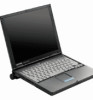
Compaq Armada m300 - Notebook PC Manual
 |
View all Compaq Armada m300 manuals
Add to My Manuals
Save this manual to your list of manuals |
Compaq Armada m300 manual content summary:
- Compaq Armada m300 | Compaq ArmadaStation EM Maintenance and Service Guide - Page 1
Compaq ArmadaStation EM Maintenance and Service Guide - Compaq Armada m300 | Compaq ArmadaStation EM Maintenance and Service Guide - Page 2
and Taiwan. COMPAQ and ARMADA are registered in the U. S. Patent and Trademark Office. Microsoft, MS-DOS, Windows, Windows NT, and other or registered trademarks of their respective companies. MAINTENANCE AND SERVICE GUIDE Compaq Expansion Base First Edition September 1999 Documentation Part Number - Compaq Armada m300 | Compaq ArmadaStation EM Maintenance and Service Guide - Page 3
Lock...1-8 PCI Expansion Boards...1-8 chapter 2 TROUBLESHOOTING Before Replacing Parts ...2-1 Problems and Solutions ...2-2 chapter 3 ILLUSTRATED PARTS Drives...4-3 Grounding Methods...4-3 Grounding Workstations ...4-4 Grounding Equipment ...4-4 Recommended Materials and Equipment 4-5 4.2 Service - Compaq Armada m300 | Compaq ArmadaStation EM Maintenance and Service Guide - Page 4
-Height Bay...5-14 Installing a Half-Height Drive...5-14 5.10 Left Speaker ...5-23 5.11 Control Bay ...5-24 5.12 Control Panel...5-26 5.13 Mechanism Assembly...5-27 5.14 Power Supply ...5-29 5.15 Backplane...5-31 chapter 6 SPECIFICATIONS ...6-1 appendix 1 CONNECTOR PIN ASSIGNMENTS ...A-1 appendix - Compaq Armada m300 | Compaq ArmadaStation EM Maintenance and Service Guide - Page 5
clarifying information or specific instructions. NOTE: Text set off in this manner presents commentary, sidelights, or interesting points of information. Technician Notes ! WARNING: Only authorized technicians trained by Compaq should attempt to repair this equipment. All troubleshooting and repair - Compaq Armada m300 | Compaq ArmadaStation EM Maintenance and Service Guide - Page 6
Information The following documentation is available to support the ArmadaStation EM: s Compaq ArmadaStation EM documentation set s Service training guides s Compaq Service Advisories and Bulletins s Compaq QuickFind s Compaq Service Quick Reference Guide s Compaq Internet site at http://www - Compaq Armada m300 | Compaq ArmadaStation EM Maintenance and Service Guide - Page 7
ArmadaStation EM provides fully integrated desktop capabilities for the Compaq Armada E and M Series of Personal Computers. The ArmadaStation EM eliminates the need to disconnect external devices when you remove the computer. NOTE: The Armada M300 computer requires the Mobile Expansion Unit (MEU) to - Compaq Armada m300 | Compaq ArmadaStation EM Maintenance and Service Guide - Page 8
, an industry-standard half-height bay, integrated stereo speakers, computer I/O port replication, motorized docking, and one full-sized and two half-sized 32-bit PCI slots. A monitor support cover capable of supporting up to 75 pounds (34 kilograms) also comes with the ArmadaStation EM. A tower - Compaq Armada m300 | Compaq ArmadaStation EM Maintenance and Service Guide - Page 9
drive, CD-ROM drive, diskette drive, SuperDisk LS-120 drive, hard drive, or extra battery pack. 11 Top MultiBay Supports a removable DVD-ROM drive, CD-ROM drive, SuperDisk LS-120 drive, or hard drive. 12 Half-height bay Supports an optional industry standard half-height device. 13 Monitor - Compaq Armada m300 | Compaq ArmadaStation EM Maintenance and Service Guide - Page 10
jack Connects a single sound channel microphone. The sound plays from both ArmadaStation EM speakers. 6 USB connectors (2) Connect universal serial bus (USB) devices. 7 Keylock Locks the computer to the ArmadaStation EM and disables the automatic docking mechanism. 8 Power button Turns the - Compaq Armada m300 | Compaq ArmadaStation EM Maintenance and Service Guide - Page 11
. 10 Security cable slot Attaches an optional security cable lock to secure the ArmadaStation EM to fixed object. 11 U-bolt Attaches an optional heavy-duty cable and lock to secure the ArmadaStation EM to a fixed object. 12 Monitor latch slot Attaches the monitor support cover rear latch - Compaq Armada m300 | Compaq ArmadaStation EM Maintenance and Service Guide - Page 12
from a removable drive inserted in the ArmadaStation EM MultiBays is accessed. Power/Suspend Light The power/suspend light is battery packs. The ArmadaStation EM MultiBays support the following devices: Device Hard Drive Diskette Drive CD-ROM drive DVD-ROM drive Battery pack SuperDisk LS-120 drive - Compaq Armada m300 | Compaq ArmadaStation EM Maintenance and Service Guide - Page 13
EM. The half-height bay supports any standard half-height drive or a half-height MultiBay adapter. Security Lock The ArmadaStation EM features a security lock that allows all computer and ArmadaStation EM resources (hard drives, diskette drives, CD-ROM drives, PCI expansion boards) to be - Compaq Armada m300 | Compaq ArmadaStation EM Maintenance and Service Guide - Page 14
2 chapter TROUBLESHOOTING This chapter contains troubleshooting information for the Compaq ArmadaStation EM. Information on how to identify and correct some common hardware, memory, and software problems is included. Troubleshooting information is covered on the following topics: s Docking and - Compaq Armada m300 | Compaq ArmadaStation EM Maintenance and Service Guide - Page 15
computer and redock it. docked or will not dock. seated in the docking system. No AC power. Release the computer from the docking mechanism by sliding the ArmadaStation EM manual release lever to the right. Table 2-2 Solving Expansion Board Problems Problem Probable Cause Recommended Action - Compaq Armada m300 | Compaq ArmadaStation EM Maintenance and Service Guide - Page 16
Device is not plug and play. For Windows 95 or Windows 98: Double-click the Add New Hardware icon in Control Panel for help installing the device. You can also use Computer Setup to install a new device. Choose Tools, Adding a Legacy Device, and follow onscreen instructions. Troubleshooting 2-3 - Compaq Armada m300 | Compaq ArmadaStation EM Maintenance and Service Guide - Page 17
than the supports. computer supports. External monitor screen is distorted. Energy Star Monitor is selected Press any key or move the mouse to restore on the Power Management the image on the screen. If the image remains menu, and the external monitor distorted, turn the monitor off, then - Compaq Armada m300 | Compaq ArmadaStation EM Maintenance and Service Guide - Page 18
3 chapter ILLUSTRATED PARTS CATALOG This chapter provides an illustrated parts breakdown and a reference for spare part numbers for the Compaq ArmadaStation EM. 3.1 Serial Number Location When ordering parts or requesting information, provide the ArmadaStation EM serial number located on the right - Compaq Armada m300 | Compaq ArmadaStation EM Maintenance and Service Guide - Page 19
3.2 Compaq ArmadaStation EM Components Figure 3-2. Compaq ArmadaStation EM Components Illustrated Parts Catalog 3-2 - Compaq Armada m300 | Compaq ArmadaStation EM Maintenance and Service Guide - Page 20
-001 5 Mechanism assembly 155270-001 MultiBay Option Cable Kit, includes: 6a Hard drive cable 6b Diskette drive cable 6c CD-ROM drive/audio cable Hard drive cable (7"; not illustrated) Drive power cable (not illustrated) 298038-001 7 Backplane 155267-001 8 Left speaker 155274 - Compaq Armada m300 | Compaq ArmadaStation EM Maintenance and Service Guide - Page 21
3.3 Plastics Kit Components Figure 3-3. Plastics Kit Components Table 3-2 Plastics Kit Components Spare Part Number 155277-001 Item Description 1 Connector cover 2 MultiBay buttons (2) Illustrated Parts Catalog 3-4 - Compaq Armada m300 | Compaq ArmadaStation EM Maintenance and Service Guide - Page 22
Option Cable Kit Figure 3-4. Cable Kit Components Table 3-3 MultiBay Option Cable Kit Components Spare Part Number 298038-001 Item Description 1 Hard drive cable 2 Hard drive cable (7" ) 3 Drive power cable 4 CD-ROM drive/audio cable 5 Diskette drive cable Illustrated Parts Catalog 3-5 - Compaq Armada m300 | Compaq ArmadaStation EM Maintenance and Service Guide - Page 23
Spare Parts: Miscellaneous (not illustrated) Description Spare Part Number Compaq ArmadaStation EM Maintenance and Service Guide 163487-001 Compaq ArmadaStation EM Screw Kit 155278-001 Carbon keyboard 118003-XX8 Carbon monitor 307710-023 PCI CardBus reader 127397-B25 Return Kit 161774 - Compaq Armada m300 | Compaq ArmadaStation EM Maintenance and Service Guide - Page 24
REPLACEMENT PRELIMINARIES This chapter provides general service information for the Compaq Expansion base. Adherence to the procedures and precautions described in this chapter is essential for proper service contains enough power to alter device parameters or melt silicon junctions. Removal and - Compaq Armada m300 | Compaq ArmadaStation EM Maintenance and Service Guide - Page 25
packaging. s Keep electrostatic sensitive parts in their containers until they arrive at static-free stations. s Place items on a grounded surface before removing them from their container. s not possible, use an ionizer to dissipate electric charges. 4-2 Removal and Replacement Preliminaries - Compaq Armada m300 | Compaq ArmadaStation EM Maintenance and Service Guide - Page 26
that have at least one inch of shock-proof foam. s Avoid touching the connectors on the hard drive. Grounding Methods The method for grounding must include either a wrist strap or a foot strap at Shielding Protection Levels Voltage 1,500 V 7,500 V 15,000 V Removal and Replacement Preliminaries 4-3 - Compaq Armada m300 | Compaq ArmadaStation EM Maintenance and Service Guide - Page 27
pins, leads, or circuitry. s Turn off power and input signals before inserting and removing connectors service tools, such as cutters, screwdrivers, and vacuums, that are conductive. s Use a portable field service compatible with most types of shoes or boots. On conductive floors or dissipative floor - Compaq Armada m300 | Compaq ArmadaStation EM Maintenance and Service Guide - Page 28
one megohm resistance s Static-dissipative table or floor mats with hard tie to ground s Field service kits s Static awareness labels s Wrist straps and footwear straps shielding bags s Transparent metallized shielding bags s Transparent shielding tubes Removal and Replacement Preliminaries 4-5 - Compaq Armada m300 | Compaq ArmadaStation EM Maintenance and Service Guide - Page 29
disassembly and assembly of the Compaq Expansion Base. Tool and Software Requirements The following tools are needed to service the Compaq power supply and backplane removal procedures) s Phillips screwdriver (for bezel cage removal and installation procedures) Screws The screws used in the Compaq - Compaq Armada m300 | Compaq ArmadaStation EM Maintenance and Service Guide - Page 30
routed in such a way that they cannot be caught or snagged by parts being removed or replaced. Handle flex cables with extreme care; they can tear easily. CAUTION: When servicing the Compaq Expansion Base, ensure that cables are placed in their proper location during the reassembly process. Improper - Compaq Armada m300 | Compaq ArmadaStation EM Maintenance and Service Guide - Page 31
PROCEDURES This chapter presents the removal and replacement procedures for the Compaq ArmadaStation EM. 5.1 Serial Number The serial number should be reported to Compaq when requesting information or ordering spare parts. The serial number is located on the right side of the ArmadaStation - Compaq Armada m300 | Compaq ArmadaStation EM Maintenance and Service Guide - Page 32
and disassembly sequence for removing components from the Compaq ArmadaStation EM. 5.3 Preparing the Expansion Base for Disassembly 5.4 5.12 Control Panel 5.13 Mechanism Assembly 5.14 Power Supply 5.15 Backplane Figure 5-2. Expansion Base Disassembly Sequence 5-2 Removal and Replacement Procedures - Compaq Armada m300 | Compaq ArmadaStation EM Maintenance and Service Guide - Page 33
the Expansion Base for Disassembly 1. Turn the expansion base keylock counterclockwise to unlock it. 2. Undock the computer from the expansion base. 3. Turn off the expansion base. 4. Disconnect the power cord from the wall outlet – (Figure 5-3). 5. Disconnect the power cord from the expansion - Compaq Armada m300 | Compaq ArmadaStation EM Maintenance and Service Guide - Page 34
5.4 External Components This section describes the removal and replacement procedures that do not require access to the internal components of the expansion base. This includes: of the expansion base (Figure 5-4). Figure 5-4. Installing the Expansion Base Feet 5-4 Removal and Replacement Procedures - Compaq Armada m300 | Compaq ArmadaStation EM Maintenance and Service Guide - Page 35
the computer should be aligned with the left side of the tray when docking the computer. 1. Prepare the expansion base for disassembly (Section 5.3). 2. Position the expansion base so the front faces forward. procedure described above to install the tray. Removal and Replacement Procedures 5-5 - Compaq Armada m300 | Compaq ArmadaStation EM Maintenance and Service Guide - Page 36
5.5 Connector Cover 1. Prepare the expansion base for disassembly (Section 5.3). 2. Position the expansion base so the rear bezel faces forward. 3. Slide the connector cover Cover Reverse the removal procedure described above to install the connector cover. 5-6 Removal and Replacement Procedures - Compaq Armada m300 | Compaq ArmadaStation EM Maintenance and Service Guide - Page 37
base for disassembly (Section 5.3). 2. Remove the connector cover (Section 5.5). 3. Slide the rear bezel release latch to the left – (Figure 5-7). 4. Swing the bottom edge of the rear bezel forward and up until it disengages —. Figure 5-7. Removing the Rear Bezel Removal and Replacement Procedures - Compaq Armada m300 | Compaq ArmadaStation EM Maintenance and Service Guide - Page 38
is moved to the right, the mechanism assembly, which secures the computer when it is docked in the expansion base, releases and allows the computer to be manually undocked. Figure 5-8. Sliding the Manual Release Lever Reverse the removal procedure described above to install the rear bezel. Before - Compaq Armada m300 | Compaq ArmadaStation EM Maintenance and Service Guide - Page 39
for 32- or 64-bit PCI expansion boards. The expansion base supports half-sized expansion boards in slots –, — and ˜; a full-sized expansion board can be installed in slot ˜ (Figure 5-9). Figure 5-9. Locating the Expansion Slots For additional information, consult the documentation included with the - Compaq Armada m300 | Compaq ArmadaStation EM Maintenance and Service Guide - Page 40
slot cover to the base cover (Figure 5-10). NOTE: Retain the expansion slot cover and screw. They will be needed if the expansion board is removed from the expansion base. 5. Remove the expansion slot cover —. Figure 5-10. Removing the Expansion Slot Cover 5-10 Removal and Replacement Procedures - Compaq Armada m300 | Compaq ArmadaStation EM Maintenance and Service Guide - Page 41
connection information. IMPORTANT: If a PCI CardBus Reader has been installed, PC Cards must be inserted label side down into the PC Card slot. For more information about using PC Cards, refer to the printed computer Reference Guide included with the computer. Removal and Replacement Procedures 5-11 - Compaq Armada m300 | Compaq ArmadaStation EM Maintenance and Service Guide - Page 42
5.8 Top Cover 1. Prepare the expansion base for disassembly (Section 5.3). 2. Remove the tray (Section 5.4). 3. Remove the connector cover (Section 5.5). 4. Remove the rear bezel (Section the base cover (Figure 5-12). Figure 5-12. Removing the Top Cover Screws 5-12 Removal and Replacement Procedures - Compaq Armada m300 | Compaq ArmadaStation EM Maintenance and Service Guide - Page 43
6. Swing the top cover up and forward to remove it (Figure 5-13). Figure 5-13. Removing the Top Cover Reverse the removal procedure described above to install the top cover. Removal and Replacement Procedures 5-13 - Compaq Armada m300 | Compaq ArmadaStation EM Maintenance and Service Guide - Page 44
the expansion base. This bay supports any standard half-height drive, such as a diskette or hard drive. Installing a Half-Height Drive 1. Prepare the expansion base for disassembly (Section 5.3). 2. Remove the base cover —. Figure 5-14. Removing the Bezel Cage 5-14 Removal and Replacement Procedures - Compaq Armada m300 | Compaq ArmadaStation EM Maintenance and Service Guide - Page 45
8. Remove the half-height bay blank bezel cover from the bezel cage (Figure 5-15). Figure 5-15. Removing the Half-Height Bay Blank Bezel Cover Removal and Replacement Procedures 5-15 - Compaq Armada m300 | Compaq ArmadaStation EM Maintenance and Service Guide - Page 46
5-16). NOTE: The half-height drive should have two screws installed in each side. If these screws are missing, appropriate-sized screws must be obtained to secure the half-height drive to the bezel cage. Figure 5-16. Removing the Half-Height Drive Screws 5-16 Removal and Replacement Procedures - Compaq Armada m300 | Compaq ArmadaStation EM Maintenance and Service Guide - Page 47
of the bezel cage – (Figure 5-17). NOTE: The bezel cage should be aligned so the "L" and "LEFT" indicators can be read when the half-height drive is installed in the expansion base left half-height bay. 11. Install the four screws — that secure the half-height - Compaq Armada m300 | Compaq ArmadaStation EM Maintenance and Service Guide - Page 48
documentation that came with the half-height drive for information about which expansion base connectors to use. 12. Connect the half-height bay power cable to the power connector on the half-height device (Figure 5-18). Figure 5-18. Connecting the Power Cable 5-18 Removal and Replacement Procedures - Compaq Armada m300 | Compaq ArmadaStation EM Maintenance and Service Guide - Page 49
13. If a diskette drive is being installed, connect the diskette drive cable to the diskette drive connector (Figure 5-19). Figure 5-19. Connecting the Diskette Drive Cable Removal and Replacement Procedures 5-19 - Compaq Armada m300 | Compaq ArmadaStation EM Maintenance and Service Guide - Page 50
14. If a hard drive is being installed, connect the hard drive cable to the hard drive connector (Figure 5-20). Figure 5-20. Connecting the Hard Drive Cable 5-20 Removal and Replacement Procedures - Compaq Armada m300 | Compaq ArmadaStation EM Maintenance and Service Guide - Page 51
15. If a CD- or DVD-ROM drive is being installed, connect the CD-ROM drive/audio cable to the connector (Figure 5-21). Figure 5-21. Connecting the CD-ROM Drive/Audio Cable Removal and Replacement Procedures 5-21 - Compaq Armada m300 | Compaq ArmadaStation EM Maintenance and Service Guide - Page 52
drive assembly into the base cover – (Figure 5-22). 17. Install the three screws — that secure the bezel cage to the base cover. Figure 5-22. Installing a Half-Height Drive Reverse the installation procedure described above to remove a half-height drive. 5-22 Removal and Replacement Procedures - Compaq Armada m300 | Compaq ArmadaStation EM Maintenance and Service Guide - Page 53
5.10 Left Speaker 1. Prepare the expansion base for disassembly (Section 5.3). 2. Remove the tray (Section 5.4). 3. Remove the rear bezel (Section 5.6). 4. Remove the top cover (Section 5.8). the removal procedure described above to install the left speaker. Removal and Replacement Procedures 5-23 - Compaq Armada m300 | Compaq ArmadaStation EM Maintenance and Service Guide - Page 54
two MultiBays on the right side of the expansion base. These MultiBays support all MultiBay devices supported by the Compaq Armada Series of Personal Computers. 1. Prepare the expansion base for disassembly (Section 5.3). 2. Remove the tray (Section 5.4). 3. Remove the connector cover (Section - Compaq Armada m300 | Compaq ArmadaStation EM Maintenance and Service Guide - Page 55
. Removing the MultiBay and Control Panel Reverse the removal procedure described above to install the MultiBay and control panel into the base cover. Removal and Replacement Procedures 5-25 - Compaq Armada m300 | Compaq ArmadaStation EM Maintenance and Service Guide - Page 56
5.12 Control Panel 1. Prepare the expansion base for disassembly (Section 5.3). 2. Remove the tray (Section 5.4). 3. Remove the connector cover (Section 5.5). 4. Remove the rear bezel (Section 5.6). 5. Remove above to attach the control panel to the MultiBay. 5-26 Removal and Replacement Procedures - Compaq Armada m300 | Compaq ArmadaStation EM Maintenance and Service Guide - Page 57
lubricant. The mechanism assembly is spared as a unit and should not be disassembled. 1. Prepare the expansion base for disassembly (Section 5.3). 2. Remove the tray (Section 5.4). 3. Remove the rear Assembly Cables and Removing the Mechanism Assembly Screws Removal and Replacement Procedures 5-27 - Compaq Armada m300 | Compaq ArmadaStation EM Maintenance and Service Guide - Page 58
of the backplane — (Figure 5-28). Figure 5-28. Removing the Mechanism Assembly Reverse the removal procedure described above to install the mechanism assembly. 5-28 Removal and Replacement Procedures - Compaq Armada m300 | Compaq ArmadaStation EM Maintenance and Service Guide - Page 59
Supply CAUTION: Do not handle or carry the power supply by the wiring harness. This can cause damage to the power supply and wiring harness. 1. Prepare the expansion base for disassembly (Section 5.3). 2. Remove the tray (Section 5.4). 3. Remove the rear bezel (Section 5.6). 4. Remove the top cover - Compaq Armada m300 | Compaq ArmadaStation EM Maintenance and Service Guide - Page 60
power supply from the base cover. 9. Route the half-height bay power supply cable through the opening in the backplane —. 10. Remove the power power supply. Figure 5-30. Removing the Power Supply Reverse the removal procedure described above to install the power supply. 5-30 Removal and Replacement - Compaq Armada m300 | Compaq ArmadaStation EM Maintenance and Service Guide - Page 61
5.15 Backplane 1. Prepare the expansion base for disassembly (Section 5.3). 2. Remove the tray (Section 5.4). 3. 5.11). 7. Remove the mechanism assembly (Section 5.13). 8. Remove the power supply (Section 5.14). 9. Remove the three screws – that secure the backplane and Replacement Procedures 5-31 - Compaq Armada m300 | Compaq ArmadaStation EM Maintenance and Service Guide - Page 62
Base Physical and Environmental Specifications U.S. Metric Dimensions Height with monitor support cover Without monitor support cover Depth with monitor support cover Without monitor support cover Width Weight with monitor support cover without monitor support cover Power Supply (Input) Operating - Compaq Armada m300 | Compaq ArmadaStation EM Maintenance and Service Guide - Page 63
The Expansion Base is designed in accordance with ANSI specifications (no. X3.131-1993, Rev 10h) and IEEE 802.3 specifications. NOTE: This product is designed for IT power systems with phase-to-phase voltage not exceeding 240Vrms minimum charge. 6-2 Specifications - Compaq Armada m300 | Compaq ArmadaStation EM Maintenance and Service Guide - Page 64
A appendix CONNECTOR PIN ASSIGNMENTS This appendix contains the pin assignments for all external connectors. Connector 12 Table A-1 Headphone Jack Pin Signal 1 Audio out 2 Ground Connector 12 Table A-2 Microphone Jack Pin Signal 1 Audio in 2 Ground Connector Pin Assignments A-1 - Compaq Armada m300 | Compaq ArmadaStation EM Maintenance and Service Guide - Page 65
Data Bit 7 10 Acknowledge 11 Busy 12 Paper End 13 Select Connector 6 5 4 KEY 3 21 Pin Signal 14 Auto Linefeed 15 Error 16 Initialize 17 Select In 18 Keyboard/Mouse Connector Pin Signal 1 Keyboard/Mouse DATA 2 Keyboard/Mouse DATA 3 Ground 4 +5 VDC 5 Keyboard/Mouse CLK 6 Keyboard - Compaq Armada m300 | Compaq ArmadaStation EM Maintenance and Service Guide - Page 66
Ground 8 Ground Connector 12 Connector 12 Table A-6 External Monitor Connector 5 43 21 10 KEY 8 7 6 15 14 13 12 11 Pin Signal 9 +5 Volt Supply 10 Ground 11 Monitor ID Bit 0 12 Monitor ID Bit 1 (SDA) 13 Horizontal Sync 14 Vertical Sync 15 Monitor ID Bit 3 (SCL) Table A-7 Stereo Line-out Jack - Compaq Armada m300 | Compaq ArmadaStation EM Maintenance and Service Guide - Page 67
14 GND 15 INDEX 16 RDATA 17 TRK0 18 WDATA 19 WGATE 20 STEP 21 DIR 22 POWER ON 23 SYS RESET 24 GND 25 DSKCHG 26 +5 V (VDD) 27 AUGND 28 XA2 XA3/R IN 30 MID0/MIC IN 31 AUGND 32 XA0/L OUT 33 XSD/MIC SN Table A-13 Docking Connector Pin Signal 34 XA1/R OUT 35 GND 36 GND 37 EXPCLK2 38 +3.3V 39 EXPCLK0 40 + - Compaq Armada m300 | Compaq ArmadaStation EM Maintenance and Service Guide - Page 68
EBOXL /GND 89 FLUSHREQ 90 MEMACK 91 PS2 VCC 92 SERIRQ 93 PS2 CLK 94 EXPREQ 95 AD[29] 96 AD[31] 97 AD[30] 98 AD[28] 99 AD[26] 100 GND 101 AD[24] 102 AD[22] 103 AD[20] 104 AD[18] Pin Signal 105 AD[16] 106 - Compaq Armada m300 | Compaq ArmadaStation EM Maintenance and Service Guide - Page 69
Table A-13 Continued Pin Signal 143 VBATT 144 AD[23] 145 GND 146 AD[21] 147 AD[19] 148 AD[17] 149 GND 150 AD[14] 151 AD[12] 152 AD[10] 153 AD[08] 154 GND 155 AD[07] 156 AD[05] 157 AD[03] 158 AD[01] 159 GND Pin Signal 160 CBE3 161 CBE2 162 IRDY 163 DEVSEL 164 LOCK 165 OERR 166 SERR 167 GND 168 RSVD3 - Compaq Armada m300 | Compaq ArmadaStation EM Maintenance and Service Guide - Page 70
other countries must meet the requirements of the country where the ArmadaStation and Armada MiniStation are used. For more information on power cord set requirements, contact a Compaq authorized reseller or service provider. General Requirements The requirements listed below are applicable to all - Compaq Armada m300 | Compaq ArmadaStation EM Maintenance and Service Guide - Page 71
Country-Specific Requirements 3-Conductor Power Cord Set Requirements-By Country Country Accredited Agency Applicable Note flexible cord must be Type HO5VV-F, 3-conductor, 1.0 mm2 conductor size. Power cord set fittings (appliance coupler and wall plug) must bear the certification mark of - Compaq Armada m300 | Compaq ArmadaStation EM Maintenance and Service Guide - Page 72
5-26 spare part number, 3-3 D depth specification, 6-1 disassembly sequence chart, 5-2 disconnecting power, 5-3 diskette drive, 1-3 cable connecting, 5-19 illustrated, 3-2, 3-5 docking connector illustrated, 1-3 pinout, A-4 drive power cable illustrated, 3-5 E electrostatic discharge, 4-1 preventing - Compaq Armada m300 | Compaq ArmadaStation EM Maintenance and Service Guide - Page 73
cable disconnecting, 5-29 power/suspend light, 1-6 illustrated, 1-3 preparing for disassembly, 5-3 preventing damage to drives, 4-3 preventing electrostatic damage, 4-2 R rated current specification, 6-1 rated line frequency specification, 6-1 rated voltage specification, 6-1 rear bezel illustrated - Compaq Armada m300 | Compaq ArmadaStation EM Maintenance and Service Guide - Page 74
, v temperature specification, 6-1 tools required for service, 4-6 top cover illustrated, 3-2 removing, 5-12 spare part number, 3-3 tower stand spare part number, 3-6 tray assembly illustrated, 3-2 removing, 5-5 spare part number, 3-3 troubleshooting, 2-1 U U-bolt illustrated, A-5 USB connectors
-
 1
1 -
 2
2 -
 3
3 -
 4
4 -
 5
5 -
 6
6 -
 7
7 -
8
-
9
-
10
-
11
-
12
-
13
-
14
-
15
-
16
-
17
-
18
-
19
-
20
-
21
-
22
-
23
-
24
-
25
-
26
-
27
-
28
-
29
-
30
-
31
-
32
-
33
-
34
-
35
-
36
-
37
-
38
-
39
-
40
-
41
-
42
-
43
-
44
-
45
-
46
-
47
-
48
-
49
-
50
-
51
-
52
-
53
-
54
-
55
-
56
-
57
-
58
-
59
-
60
-
61
-
62
-
63
-
64
-
65
-
66
-
67
-
68
-
69
-
70
-
71
-
72
-
73
-
74
 |
 |
Compaq ArmadaStation EM
Maintenance and Service Guide