Compaq Evo n1050v Service Manual - Page 100
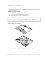
Caution, Removing the Top Case Screws, HP Pavilion 5300 and 5200, HP nx9010
 |
View all Compaq Evo n1050v manuals
Add to My Manuals
Save this manual to your list of manuals |
Page 100 highlights
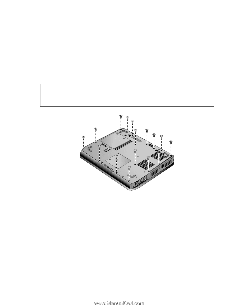
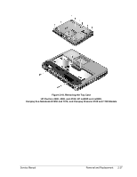
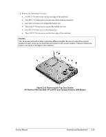
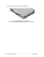
4. Remove the following 16 screws: • Six M2.5×7.0 mm screws on the rear edge of the notebook. • Two M2.5×6.0 mm screws on each side of the docking connector. • One M2.5×6.0 mm screw behind the battery bay. • Three M2.5×7.0 mm screws around the middle fan vent. • One M2.5×4.0 mm screw in the battery bay. • Three M2.5×7.0 mm screws on the front edge of the notebook. Caution The 16 screws removed in Step 4 are three different lengths. Be sure to note of the correct location of each screw as it is removed and install it in the correct location. Failure to follow this caution can result in damage to the notebook. Figure 2-19. Removing the Top Case Screws HP Pavilion 5300 and 5200, HP nx9010, and Compaq Presario 2500 Models Service Manual Removal and Replacement 2-29
-
 1
1 -
2
-
3
-
4
-
5
-
6
-
7
-
8
-
9
-
10
-
11
-
12
-
13
-
14
-
15
-
16
-
17
-
18
-
19
-
20
-
21
-
22
-
23
-
24
-
25
-
26
-
27
-
28
-
29
-
30
-
31
-
32
-
33
-
34
-
35
-
36
-
37
-
38
-
39
-
40
-
41
-
42
-
43
-
44
-
45
-
46
-
47
-
48
-
49
-
50
-
51
-
52
-
53
-
54
-
55
-
56
-
57
-
58
-
59
-
60
-
61
-
62
-
63
-
64
-
65
-
66
-
67
-
68
-
69
-
70
-
71
-
72
-
73
-
74
-
75
-
76
-
77
-
78
-
79
-
80
-
81
-
82
-
83
-
84
-
85
-
86
-
87
-
88
-
89
-
90
-
91
-
92
-
93
-
94
-
 95
95 -
 96
96 -
 97
97 -
 98
98 -
 99
99 -
 100
100 -
 101
101 -
 102
102 -
 103
103 -
 104
104 -
 105
105 -
106
-
107
-
108
-
109
-
110
-
111
-
112
-
113
-
114
-
115
-
116
-
117
-
118
-
119
-
120
-
121
-
122
-
123
-
124
-
125
-
126
-
127
-
128
-
129
-
130
-
131
-
132
-
133
-
134
-
135
-
136
-
137
-
138
-
139
-
140
-
141
-
142
-
143
-
144
-
145
-
146
-
147
-
148
-
149
-
150
-
151
-
152
-
153
-
154
-
155
-
156
-
157
-
158
-
159
-
160
-
161
-
162
-
163
-
164
-
165
-
166
-
167
-
168
-
169
-
170
-
171
-
172
-
173
-
174
-
175
-
176
-
177
-
178
-
179
-
180
-
181
-
182
-
183
-
184
-
185
-
186
-
187
-
188
 |
 |