Compaq Evo n1050v Service Manual - Page 124
Removing the Hard Disk Drive Guide
 |
View all Compaq Evo n1050v manuals
Add to My Manuals
Save this manual to your list of manuals |
Page 124 highlights
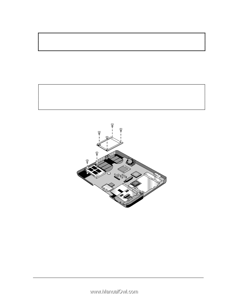
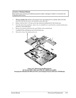
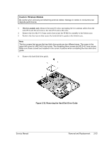
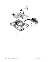
Caution: Wireless Models Be careful when removing and attaching antenna cables. Damage to cables or connectors can degrade performance. 3. Wireless models only: Remove the mini-PCI door and unplug the two antenna cables from the mini-PCI card. Do not remove the mini-PCI card at this time. 4. Remove the two M2.0×4.0 mm screws that secure the PCMCIA assembly to the bottom case. 5. Remove the four screws that secure the hard disk drive guide to the bottom case. Note The four screws that secure the hard disk drive guide are two different sizes. The screw in the upper left corner is a M2.5×6.0 mm screw. The remaining three screws are M2.0×4.0 mm screws. Make sure these screws are installed in the correct locations when reinstalling the hard disk drive guide. 6. Remove the hard disk drive guide. Figure 2-32. Removing the Hard Disk Drive Guide Service Manual Removal and Replacement 2-53
-
 1
1 -
2
-
3
-
4
-
5
-
6
-
7
-
8
-
9
-
10
-
11
-
12
-
13
-
14
-
15
-
16
-
17
-
18
-
19
-
20
-
21
-
22
-
23
-
24
-
25
-
26
-
27
-
28
-
29
-
30
-
31
-
32
-
33
-
34
-
35
-
36
-
37
-
38
-
39
-
40
-
41
-
42
-
43
-
44
-
45
-
46
-
47
-
48
-
49
-
50
-
51
-
52
-
53
-
54
-
55
-
56
-
57
-
58
-
59
-
60
-
61
-
62
-
63
-
64
-
65
-
66
-
67
-
68
-
69
-
70
-
71
-
72
-
73
-
74
-
75
-
76
-
77
-
78
-
79
-
80
-
81
-
82
-
83
-
84
-
85
-
86
-
87
-
88
-
89
-
90
-
91
-
92
-
93
-
94
-
95
-
96
-
97
-
98
-
99
-
100
-
101
-
102
-
103
-
104
-
105
-
106
-
107
-
108
-
109
-
110
-
111
-
112
-
113
-
114
-
115
-
116
-
117
-
118
-
 119
119 -
 120
120 -
 121
121 -
 122
122 -
 123
123 -
 124
124 -
 125
125 -
 126
126 -
 127
127 -
 128
128 -
 129
129 -
130
-
131
-
132
-
133
-
134
-
135
-
136
-
137
-
138
-
139
-
140
-
141
-
142
-
143
-
144
-
145
-
146
-
147
-
148
-
149
-
150
-
151
-
152
-
153
-
154
-
155
-
156
-
157
-
158
-
159
-
160
-
161
-
162
-
163
-
164
-
165
-
166
-
167
-
168
-
169
-
170
-
171
-
172
-
173
-
174
-
175
-
176
-
177
-
178
-
179
-
180
-
181
-
182
-
183
-
184
-
185
-
186
-
187
-
188
 |
 |