Compaq Evo n1050v Service Manual - Page 126
on the left edge of the motherboard that secure the motherboard to the bottom case.
 |
View all Compaq Evo n1050v manuals
Add to My Manuals
Save this manual to your list of manuals |
Page 126 highlights
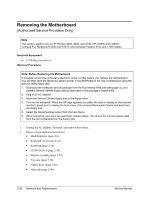
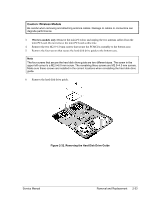
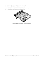
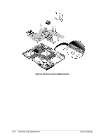
11. Remove the four M5.0×10.mm standoffs from the notebook rear panel (two on each side of the parallel and external monitor connectors). 12. Remove the three M2.5×6.0 mm screws that secure the CD/DVD drive rear alignment rail to the bottom case. 13. Remove the CD/DVD drive rear alignment rail. 14. Remove the two screws that secure the CD/DVD drive front alignment rail to the bottom case. Note The two screws that secure the CD/DVD drive front alignment rail to the bottom case are two different sizes. The screw that secures the left side of the rail is a M2.0×4.0 mm screw. The screw that secures the right side of the rail is a M2.5×6.0 mm countersink screw. Make sure these screws are installed in the correct locations when reinstalling the CD/DVD drive front alignment rail. 15. Remove the CD/DVD drive front alignment rail. 16. Remove the two M2.5×6.0 countersink screws (one on the front edge of the motherboard, the other on the left edge of the motherboard) that secure the motherboard to the bottom case. 17. Remove the two M2.0×5.0 screws that secure the motherboard to the bottom case on the back edge of the motherboard. 18. Remove the antenna cable from the metal holder on the motherboard. 19. Carefully lift the motherboard out of the bottom case. 20. If present, remove the modem port cover. Service Manual Removal and Replacement 2-55
-
 1
1 -
2
-
3
-
4
-
5
-
6
-
7
-
8
-
9
-
10
-
11
-
12
-
13
-
14
-
15
-
16
-
17
-
18
-
19
-
20
-
21
-
22
-
23
-
24
-
25
-
26
-
27
-
28
-
29
-
30
-
31
-
32
-
33
-
34
-
35
-
36
-
37
-
38
-
39
-
40
-
41
-
42
-
43
-
44
-
45
-
46
-
47
-
48
-
49
-
50
-
51
-
52
-
53
-
54
-
55
-
56
-
57
-
58
-
59
-
60
-
61
-
62
-
63
-
64
-
65
-
66
-
67
-
68
-
69
-
70
-
71
-
72
-
73
-
74
-
75
-
76
-
77
-
78
-
79
-
80
-
81
-
82
-
83
-
84
-
85
-
86
-
87
-
88
-
89
-
90
-
91
-
92
-
93
-
94
-
95
-
96
-
97
-
98
-
99
-
100
-
101
-
102
-
103
-
104
-
105
-
106
-
107
-
108
-
109
-
110
-
111
-
112
-
113
-
114
-
115
-
116
-
117
-
118
-
119
-
120
-
 121
121 -
 122
122 -
 123
123 -
 124
124 -
 125
125 -
 126
126 -
 127
127 -
 128
128 -
 129
129 -
 130
130 -
 131
131 -
132
-
133
-
134
-
135
-
136
-
137
-
138
-
139
-
140
-
141
-
142
-
143
-
144
-
145
-
146
-
147
-
148
-
149
-
150
-
151
-
152
-
153
-
154
-
155
-
156
-
157
-
158
-
159
-
160
-
161
-
162
-
163
-
164
-
165
-
166
-
167
-
168
-
169
-
170
-
171
-
172
-
173
-
174
-
175
-
176
-
177
-
178
-
179
-
180
-
181
-
182
-
183
-
184
-
185
-
186
-
187
-
188
 |
 |