Compaq Evo n1050v Service Manual - Page 94
Removing the Display Assembly, Authorized Service Providers Only
 |
View all Compaq Evo n1050v manuals
Add to My Manuals
Save this manual to your list of manuals |
Page 94 highlights
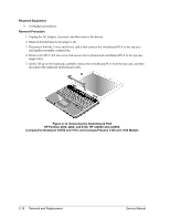
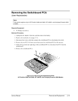
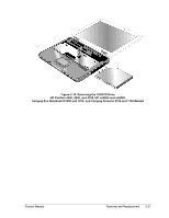
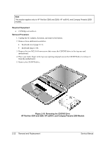
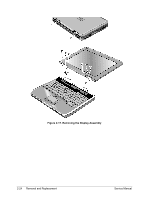
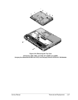
Removing the Display Assembly (Authorized Service Providers Only) Required Equipment • #1 Phillips screwdriver. Removal Procedure 1. Unplug the AC adapter, if present, and remove the battery. 2. Remove the keyboard cover (page 2-12). 3. Remove the two M2.5×6.0 mm retaining screws from the notebook rear panel. 4. Remove the M2.5×4.0 mm screws from the left and right antenna PCAs. Relocate the antenna PCAs away from the display assembly hinges. 5. Disconnect the display assembly cable from the motherboard. 6. Remove the six M2.5×6.0 mm retaining screws that secure the display assembly to the top case. Note that there is a grounding strap at the left hinge. 7. Lift the display assembly off of the notebook. Service Manual Removal and Replacement 2-23
-
 1
1 -
2
-
3
-
4
-
5
-
6
-
7
-
8
-
9
-
10
-
11
-
12
-
13
-
14
-
15
-
16
-
17
-
18
-
19
-
20
-
21
-
22
-
23
-
24
-
25
-
26
-
27
-
28
-
29
-
30
-
31
-
32
-
33
-
34
-
35
-
36
-
37
-
38
-
39
-
40
-
41
-
42
-
43
-
44
-
45
-
46
-
47
-
48
-
49
-
50
-
51
-
52
-
53
-
54
-
55
-
56
-
57
-
58
-
59
-
60
-
61
-
62
-
63
-
64
-
65
-
66
-
67
-
68
-
69
-
70
-
71
-
72
-
73
-
74
-
75
-
76
-
77
-
78
-
79
-
80
-
81
-
82
-
83
-
84
-
85
-
86
-
87
-
88
-
 89
89 -
 90
90 -
 91
91 -
 92
92 -
 93
93 -
 94
94 -
 95
95 -
 96
96 -
 97
97 -
 98
98 -
 99
99 -
100
-
101
-
102
-
103
-
104
-
105
-
106
-
107
-
108
-
109
-
110
-
111
-
112
-
113
-
114
-
115
-
116
-
117
-
118
-
119
-
120
-
121
-
122
-
123
-
124
-
125
-
126
-
127
-
128
-
129
-
130
-
131
-
132
-
133
-
134
-
135
-
136
-
137
-
138
-
139
-
140
-
141
-
142
-
143
-
144
-
145
-
146
-
147
-
148
-
149
-
150
-
151
-
152
-
153
-
154
-
155
-
156
-
157
-
158
-
159
-
160
-
161
-
162
-
163
-
164
-
165
-
166
-
167
-
168
-
169
-
170
-
171
-
172
-
173
-
174
-
175
-
176
-
177
-
178
-
179
-
180
-
181
-
182
-
183
-
184
-
185
-
186
-
187
-
188
 |
 |