Compaq M700 Compaq ArmadaStation EM Maintenance and Service Guide
Compaq M700 - Armada - PIII 650 MHz Manual
 |
View all Compaq M700 manuals
Add to My Manuals
Save this manual to your list of manuals |
Compaq M700 manual content summary:
- Compaq M700 | Compaq ArmadaStation EM Maintenance and Service Guide - Page 1
Compaq ArmadaStation EM Maintenance and Service Guide - Compaq M700 | Compaq ArmadaStation EM Maintenance and Service Guide - Page 2
Singapore, and Taiwan. COMPAQ and ARMADA are registered in the U. S. Patent and Trademark Office. Microsoft, MS-DOS, Windows, Windows NT, and other AND SERVICE GUIDE Compaq Expansion Base First Edition September 1999 Documentation Part Number 144098-001 Spare Part Number 163487-001 Compaq Computer - Compaq M700 | Compaq ArmadaStation EM Maintenance and Service Guide - Page 3
2 TROUBLESHOOTING Before Replacing Parts ...2-1 Problems and Solutions ...2-2 chapter 3 ILLUSTRATED PARTS CATALOG 3.1 Serial Number Location...3-1 3.2 Drives...4-3 Grounding Methods...4-3 Grounding Workstations ...4-4 Grounding Equipment ...4-4 Recommended Materials and Equipment 4-5 4.2 Service - Compaq M700 | Compaq ArmadaStation EM Maintenance and Service Guide - Page 4
Parts...4-7 chapter 5 EXPANSION BASE REMOVAL AND REPLACEMENT PROCEDURES 5.1 Serial Number ...5-1 5.2 Disassembly Sequence Chart...5-2 5.3 Preparing the Expansion Base for Disassembly a Half-Height Drive...5-14 5.10 Left Speaker ...5-23 5.11 Control Bay ...5-24 5.12 Control Panel...5-26 5.13 - Compaq M700 | Compaq ArmadaStation EM Maintenance and Service Guide - Page 5
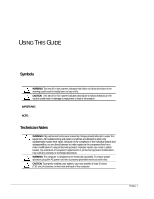
GUIDE This Maintenance and Service Guide is a troubleshooting guide that can be used for reference when servicing the Compaq ArmadaStation EM. Compaq Computer Corporation reserves the right to make changes to the Compaq . Any indication of component replacement or printed wiring board modifications - Compaq M700 | Compaq ArmadaStation EM Maintenance and Service Guide - Page 6
. Locating Additional Information The following documentation is available to support the ArmadaStation EM: s Compaq ArmadaStation EM documentation set s Service training guides s Compaq Service Advisories and Bulletins s Compaq QuickFind s Compaq Service Quick Reference Guide s Compaq Internet site - Compaq M700 | Compaq ArmadaStation EM Maintenance and Service Guide - Page 7
ArmadaStation EM provides fully integrated desktop capabilities for the Compaq Armada E and M Series of Personal Computers. The ArmadaStation EM eliminates the need to disconnect external devices when you remove the computer. NOTE: The Armada M300 computer requires the Mobile Expansion Unit (MEU) to - Compaq M700 | Compaq ArmadaStation EM Maintenance and Service Guide - Page 8
panel release latch to prevent access to the computer manual eject button and PCI slots, and disables the MultiBay release buttons. External Connectors s Docking connector s Serial connector s Parallel connector s External mouse connector s External keyboard connector s External CRT connector for - Compaq M700 | Compaq ArmadaStation EM Maintenance and Service Guide - Page 9
the bottom MultiBay. 10 Bottom MultiBay Supports a removable DVD-ROM drive, CD-ROM drive, diskette drive, SuperDisk LS-120 drive, hard drive, or extra battery pack. 11 Top MultiBay Supports a removable DVD-ROM drive, CD-ROM drive, SuperDisk LS-120 drive, or hard drive. 12 Half-height bay - Compaq M700 | Compaq ArmadaStation EM Maintenance and Service Guide - Page 10
EM docking connector. 2 Volume control switch Adjusts or mutes the volume of the stereo speakers or audio equipment. To mute, press between the - and + symbols. 3 Stereo speaker/headphone jack Connects stereo speakers, headphones, or a headset. 4 Stereo line-in jack Connects a CD player - Compaq M700 | Compaq ArmadaStation EM Maintenance and Service Guide - Page 11
Item Description Function 1 Keyboard connector Connects an external keyboard. 2 Mouse connector Connects an external mouse. 3 Serial connector Connects a serial device such as a fixed object. 12 Monitor latch slot Attaches the monitor support cover rear latch. Product Description 1-5 - Compaq M700 | Compaq ArmadaStation EM Maintenance and Service Guide - Page 12
hard drive adapter), CD-ROM drives, DVD-ROM drives, diskette drives (bottom MultiBay only), and SuperDisk LS-120 drives. The bottom MultiBay can also be used to charge MultiBay battery packs. The ArmadaStation EM MultiBays support the following devices: Device Hard Drive Diskette Drive CD-ROM drive - Compaq M700 | Compaq ArmadaStation EM Maintenance and Service Guide - Page 13
is located on the front of the ArmadaStation EM. The half-height bay supports any standard half-height drive or a half-height MultiBay adapter. Security Lock The ArmadaStation EM features a security lock that allows all computer and ArmadaStation EM resources (hard drives, diskette drives, CD-ROM - Compaq M700 | Compaq ArmadaStation EM Maintenance and Service Guide - Page 14
the problem is solved. Before Replacing Parts When troubleshooting a problem, check the following list for possible solutions before replacing parts: s Verify that cables are connected properly to the suspected defective parts. s Verify that all required device drivers are installed. Troubleshooting - Compaq M700 | Compaq ArmadaStation EM Maintenance and Service Guide - Page 15
and Solutions Table 2-1 Solving Docking and Undocking Problems Problem Probable Cause Recommended Action(s) The computer will not undock The operating system (such as from the ArmadaStation EM. Windows NT) does not support undocking while the computer is on or in Suspend. Exit all applications - Compaq M700 | Compaq ArmadaStation EM Maintenance and Service Guide - Page 16
Device is not plug and play. For Windows 95 or Windows 98: Double-click the Add New Hardware icon in Control Panel for help installing the device. You can also use Computer Setup to install a new device. Choose Tools, Adding a Legacy Device, and follow onscreen instructions. Troubleshooting 2-3 - Compaq M700 | Compaq ArmadaStation EM Maintenance and Service Guide - Page 17
the computer using higher resolution than the supports. computer supports. External monitor screen is distorted. Energy Star Monitor is selected Press any key or move the mouse to restore on the Power Management the image on the screen. If the image remains menu, and the external monitor distorted - Compaq M700 | Compaq ArmadaStation EM Maintenance and Service Guide - Page 18
CATALOG This chapter provides an illustrated parts breakdown and a reference for spare part numbers for the Compaq ArmadaStation EM. 3.1 Serial Number Location When ordering parts or requesting information, provide the ArmadaStation EM serial number located on the right side of the expansion base - Compaq M700 | Compaq ArmadaStation EM Maintenance and Service Guide - Page 19
3.2 Compaq ArmadaStation EM Components Figure 3-2. Compaq ArmadaStation EM Components Illustrated Parts Catalog 3-2 - Compaq M700 | Compaq ArmadaStation EM Maintenance and Service Guide - Page 20
: 6a Hard drive cable 6b Diskette drive cable 6c CD-ROM drive/audio cable Hard drive cable (7"; not illustrated) Drive power cable (not illustrated) 298038-001 7 Backplane 155267-001 8 Left speaker 155274-001 9 MultiBay 155271-001 10 Bezel cage 155273-001 11 Control panel - Compaq M700 | Compaq ArmadaStation EM Maintenance and Service Guide - Page 21
3.3 Plastics Kit Components Figure 3-3. Plastics Kit Components Table 3-2 Plastics Kit Components Spare Part Number 155277-001 Item Description 1 Connector cover 2 MultiBay buttons (2) Illustrated Parts Catalog 3-4 - Compaq M700 | Compaq ArmadaStation EM Maintenance and Service Guide - Page 22
Option Cable Kit Figure 3-4. Cable Kit Components Table 3-3 MultiBay Option Cable Kit Components Spare Part Number 298038-001 Item Description 1 Hard drive cable 2 Hard drive cable (7" ) 3 Drive power cable 4 CD-ROM drive/audio cable 5 Diskette drive cable Illustrated Parts Catalog 3-5 - Compaq M700 | Compaq ArmadaStation EM Maintenance and Service Guide - Page 23
3.5 Miscellaneous Table 3-4 Spare Parts: Miscellaneous (not illustrated) Description Spare Part Number Compaq ArmadaStation EM Maintenance and Service Guide 163487-001 Compaq ArmadaStation EM Screw Kit 155278-001 Carbon keyboard 118003-XX8 Carbon monitor 307710-023 PCI CardBus reader - Compaq M700 | Compaq ArmadaStation EM Maintenance and Service Guide - Page 24
4 chapter REMOVAL AND REPLACEMENT PRELIMINARIES This chapter provides general service information for the Compaq Expansion base. Adherence to the procedures and precautions described in this chapter is essential for proper service. 4.1 Electrostatic Discharge A sudden discharge of static electricity - Compaq M700 | Compaq ArmadaStation EM Maintenance and Service Guide - Page 25
electrostatic sensitive parts and assemblies with nonconductive or approved containers or packaging. s Keep electrostatic sensitive parts in their containers until they arrive at static-free stations. s , use an ionizer to dissipate electric charges. 4-2 Removal and Replacement Preliminaries - Compaq M700 | Compaq ArmadaStation EM Maintenance and Service Guide - Page 26
of shock-proof foam. s Avoid touching the connectors on the hard drive. Grounding Methods The method for grounding must include either a wrist strap or a foot strap at a grounded workstation. When seated, wear a wrist strap connected to a grounded system. When standing, use footstraps and a grounded - Compaq M700 | Compaq ArmadaStation EM Maintenance and Service Guide - Page 27
wrist strap connected to the electrostatic sensitive components, parts, and assemblies by service tools, such as cutters, screwdrivers, and vacuums, that are conductive. s Use a portable field service without banana-plug connectors, connect a wrist strap with of shoes or boots. On conductive floors - Compaq M700 | Compaq ArmadaStation EM Maintenance and Service Guide - Page 28
one megohm resistance s Static-dissipative table or floor mats with hard tie to ground s Field service kits s Static awareness labels s Wrist straps and footwear straps shielding bags s Transparent metallized shielding bags s Transparent shielding tubes Removal and Replacement Preliminaries 4-5 - Compaq M700 | Compaq ArmadaStation EM Maintenance and Service Guide - Page 29
during the reassembly process, it can damage the unit. Compaq strongly recommends that all screws removed during disassembly be kept with the part that was removed, then returned to their proper locations. CAUTION: When servicing the Compaq Expansion Base, ensure that all screws are kept with the - Compaq M700 | Compaq ArmadaStation EM Maintenance and Service Guide - Page 30
that they cannot be caught or snagged by parts being removed or replaced. Handle flex cables with extreme care; they can tear easily. CAUTION: When servicing the Compaq Expansion Base, ensure that cables are placed in their proper location during the reassembly process. Improper cable placement can - Compaq M700 | Compaq ArmadaStation EM Maintenance and Service Guide - Page 31
PROCEDURES This chapter presents the removal and replacement procedures for the Compaq ArmadaStation EM. 5.1 Serial Number The serial number should be reported to Compaq when requesting information or ordering spare parts. The serial number is located on the right side of the ArmadaStation - Compaq M700 | Compaq ArmadaStation EM Maintenance and Service Guide - Page 32
Feet Tray 5.5 Connector Cover 5.6 Rear Bezel 5.7 PCI Expansion Boards 5.8 Top Cover 5.9 Half-Height Bay 5.10 Left Speaker 5.11 MultiBay 5.12 Control Panel 5.13 Mechanism Assembly 5.14 Power Supply 5.15 Backplane Figure 5-2. Expansion Base Disassembly Sequence 5-2 Removal and Replacement Procedures - Compaq M700 | Compaq ArmadaStation EM Maintenance and Service Guide - Page 33
5.3 Preparing the Expansion Base for Disassembly 1. Turn the expansion base keylock counterclockwise to unlock it. 2. Undock the computer from the expansion base external devices. 7. If installed, remove any MultiBay devices from the expansion base MultiBays. Removal and Replacement Procedures 5-3 - Compaq M700 | Compaq ArmadaStation EM Maintenance and Service Guide - Page 34
5.4 External Components This section describes the removal and replacement procedures that do not require access to the internal components of the expansion base. This includes: s Expansion base base (Figure 5-4). Figure 5-4. Installing the Expansion Base Feet 5-4 Removal and Replacement Procedures - Compaq M700 | Compaq ArmadaStation EM Maintenance and Service Guide - Page 35
be aligned with the left side of the tray when docking the computer. 1. Prepare the expansion base for disassembly (Section 5.3). 2. Position the expansion base so the front faces forward. 3. Remove the label – and screw — located behind the retaining latch ˜ (Figure 5-5). 4. Pull forward ™ on the - Compaq M700 | Compaq ArmadaStation EM Maintenance and Service Guide - Page 36
5.5 Connector Cover 1. Prepare the expansion base for disassembly (Section 5.3). 2. Position the expansion base so the rear bezel faces forward. 3. Slide the connector cover Cover Reverse the removal procedure described above to install the connector cover. 5-6 Removal and Replacement Procedures - Compaq M700 | Compaq ArmadaStation EM Maintenance and Service Guide - Page 37
base for disassembly (Section 5.3). 2. Remove the connector cover (Section 5.5). 3. Slide the rear bezel release latch to the left – (Figure 5-7). 4. Swing the bottom edge of the rear bezel forward and up until it disengages —. Figure 5-7. Removing the Rear Bezel Removal and Replacement Procedures - Compaq M700 | Compaq ArmadaStation EM Maintenance and Service Guide - Page 38
the rear bezel has been removed, the manual release lever is accessible (Figure 5-8). When this lever is moved to the right, the mechanism assembly, which secures the computer when it is docked in the expansion base, releases and allows the computer to be manually undocked. Figure 5-8. Sliding the - Compaq M700 | Compaq ArmadaStation EM Maintenance and Service Guide - Page 39
supports half-sized expansion boards in slots –, — and ˜; a full-sized expansion board can be installed in slot ˜ (Figure 5-9). Figure 5-9. Locating for disassembly (Section 5.3). 2. Remove the connector cover (Section 5.5). 3. Remove the rear bezel (Section 5.6). Removal and Replacement Procedures - Compaq M700 | Compaq ArmadaStation EM Maintenance and Service Guide - Page 40
if the expansion board is removed from the expansion base. 5. Remove the expansion slot cover —. Figure 5-10. Removing the Expansion Slot Cover 5-10 Removal and Replacement Procedures - Compaq M700 | Compaq ArmadaStation EM Maintenance and Service Guide - Page 41
an expansion board has been installed, its internal connector can be accessed on the lower right side of the expansion base. If the board has a cable, refer to the documentation included with the board for connection information. IMPORTANT: If a PCI CardBus Reader has been installed, PC Cards - Compaq M700 | Compaq ArmadaStation EM Maintenance and Service Guide - Page 42
5.8 Top Cover 1. Prepare the expansion base for disassembly (Section 5.3). 2. Remove the tray (Section 5.4). 3. Remove the connector cover (Section 5.5). 4. Remove the rear bezel (Section the base cover (Figure 5-12). Figure 5-12. Removing the Top Cover Screws 5-12 Removal and Replacement Procedures - Compaq M700 | Compaq ArmadaStation EM Maintenance and Service Guide - Page 43
6. Swing the top cover up and forward to remove it (Figure 5-13). Figure 5-13. Removing the Top Cover Reverse the removal procedure described above to install the top cover. Removal and Replacement Procedures 5-13 - Compaq M700 | Compaq ArmadaStation EM Maintenance and Service Guide - Page 44
located on the left side of the expansion base. This bay supports any standard half-height drive, such as a diskette or hard drive. Installing a Half-Height Drive 1. Prepare the expansion base for disassembly base cover —. Figure 5-14. Removing the Bezel Cage 5-14 Removal and Replacement Procedures - Compaq M700 | Compaq ArmadaStation EM Maintenance and Service Guide - Page 45
8. Remove the half-height bay blank bezel cover from the bezel cage (Figure 5-15). Figure 5-15. Removing the Half-Height Bay Blank Bezel Cover Removal and Replacement Procedures 5-15 - Compaq M700 | Compaq ArmadaStation EM Maintenance and Service Guide - Page 46
5-16). NOTE: The half-height drive should have two screws installed in each side. If these screws are missing, appropriate-sized screws must be obtained to secure the half-height drive to the bezel cage. Figure 5-16. Removing the Half-Height Drive Screws 5-16 Removal and Replacement Procedures - Compaq M700 | Compaq ArmadaStation EM Maintenance and Service Guide - Page 47
of the bezel cage – (Figure 5-17). NOTE: The bezel cage should be aligned so the "L" and "LEFT" indicators can be read when the half-height drive is installed in the expansion base left half-height bay. 11. Install the four screws — that secure the half-height - Compaq M700 | Compaq ArmadaStation EM Maintenance and Service Guide - Page 48
documentation that came with the half-height drive for information about which expansion base connectors to use. 12. Connect the half-height bay power cable to the power connector on the half-height device (Figure 5-18). Figure 5-18. Connecting the Power Cable 5-18 Removal and Replacement Procedures - Compaq M700 | Compaq ArmadaStation EM Maintenance and Service Guide - Page 49
13. If a diskette drive is being installed, connect the diskette drive cable to the diskette drive connector (Figure 5-19). Figure 5-19. Connecting the Diskette Drive Cable Removal and Replacement Procedures 5-19 - Compaq M700 | Compaq ArmadaStation EM Maintenance and Service Guide - Page 50
14. If a hard drive is being installed, connect the hard drive cable to the hard drive connector (Figure 5-20). Figure 5-20. Connecting the Hard Drive Cable 5-20 Removal and Replacement Procedures - Compaq M700 | Compaq ArmadaStation EM Maintenance and Service Guide - Page 51
15. If a CD- or DVD-ROM drive is being installed, connect the CD-ROM drive/audio cable to the connector (Figure 5-21). Figure 5-21. Connecting the CD-ROM Drive/Audio Cable Removal and Replacement Procedures 5-21 - Compaq M700 | Compaq ArmadaStation EM Maintenance and Service Guide - Page 52
drive assembly into the base cover – (Figure 5-22). 17. Install the three screws — that secure the bezel cage to the base cover. Figure 5-22. Installing a Half-Height Drive Reverse the installation procedure described above to remove a half-height drive. 5-22 Removal and Replacement Procedures - Compaq M700 | Compaq ArmadaStation EM Maintenance and Service Guide - Page 53
5.10 Left Speaker 1. Prepare the expansion base for disassembly (Section 5.3). 2. Remove the tray (Section 5.4). 3. Remove the rear bezel (Section 5.6). 4. Remove the top cover (Section 5.8). the removal procedure described above to install the left speaker. Removal and Replacement Procedures 5-23 - Compaq M700 | Compaq ArmadaStation EM Maintenance and Service Guide - Page 54
expansion base for disassembly (Section 5.3). 2. Remove the tray (Section 5.4). 3. Remove the connector cover (Section 5.5). 4. Remove the rear bezel (Section 5.6). 5. Remove the top cover (Section 5.8). 6. Disconnect the left speaker –, CD-ROM/audio —, hard drive ˜, and diskette drive cables ™ from - Compaq M700 | Compaq ArmadaStation EM Maintenance and Service Guide - Page 55
secure the MultiBay and control panel to the base cover (Figure 5-25). NOTE: The screws removed in this step are two different sizes: four screws – are Torx T10 screws; the other two screws — are Torx T15 screws. Be sure to install these screws in the correct locations when reinstalling the MultiBay - Compaq M700 | Compaq ArmadaStation EM Maintenance and Service Guide - Page 56
5.12 Control Panel 1. Prepare the expansion base for disassembly (Section 5.3). 2. Remove the tray (Section 5.4). 3. Remove the connector cover ( that secures the control panel to the MultiBay —. 9. Remove the control panel from the MultiBay ˜. Figure 5-26. Removing the Control Panel Reverse the - Compaq M700 | Compaq ArmadaStation EM Maintenance and Service Guide - Page 57
lubricant. The mechanism assembly is spared as a unit and should not be disassembled. 1. Prepare the expansion base for disassembly (Section 5.3). 2. Remove the tray (Section 5.4). 3. Remove the rear Assembly Cables and Removing the Mechanism Assembly Screws Removal and Replacement Procedures 5-27 - Compaq M700 | Compaq ArmadaStation EM Maintenance and Service Guide - Page 58
of the backplane — (Figure 5-28). Figure 5-28. Removing the Mechanism Assembly Reverse the removal procedure described above to install the mechanism assembly. 5-28 Removal and Replacement Procedures - Compaq M700 | Compaq ArmadaStation EM Maintenance and Service Guide - Page 59
supply and wiring harness. 1. Prepare the expansion base for disassembly (Section 5.3). 2. Remove the tray (Section 5.4). 3. Remove Remove the top cover (Section 5.8). 5. Disconnect the power supply cable connected to the backplane –. 6. Remove the four screws — that secure Replacement Procedures 5-29 - Compaq M700 | Compaq ArmadaStation EM Maintenance and Service Guide - Page 60
to remove the power supply. Figure 5-30. Removing the Power Supply Reverse the removal procedure described above to install the power supply. 5-30 Removal and Replacement Procedures - Compaq M700 | Compaq ArmadaStation EM Maintenance and Service Guide - Page 61
5.15 Backplane 1. Prepare the expansion base for disassembly (Section 5.3). 2. Remove the tray (Section 5.4). 3. Remove the rear bezel (Section 5.6). 4. If installed, remove any Backplane Reverse the removal procedure described above to install the backplane. Removal and Replacement Procedures 5-31 - Compaq M700 | Compaq ArmadaStation EM Maintenance and Service Guide - Page 62
Rated Line Frequency Temperature Operating Nonoperating Relative Humidity Operating Nonoperating Altitude Operating Nonoperating Shock Operating Nonoperating Vibration Operating Nonoperating Monitor support cover(maximum) 5.7 in 5.0 in 17.5 in. 16.2 in. 18.0 in 24.9 lb 19.2 lb 90 to 260 VAC 5.0 Amp - Compaq M700 | Compaq ArmadaStation EM Maintenance and Service Guide - Page 63
The Expansion Base is designed in accordance with ANSI specifications (no. X3.131-1993, Rev 10h) and IEEE 802.3 specifications. NOTE: This product is designed for IT power systems with phase-to-phase voltage not exceeding 240Vrms minimum charge. 6-2 Specifications - Compaq M700 | Compaq ArmadaStation EM Maintenance and Service Guide - Page 64
A appendix CONNECTOR PIN ASSIGNMENTS This appendix contains the pin assignments for all external connectors. Connector 12 Table A-1 Headphone Jack Pin Signal 1 Audio out 2 Ground Connector 12 Table A-2 Microphone Jack Pin Signal 1 Audio in 2 Ground Connector Pin Assignments A-1 - Compaq M700 | Compaq ArmadaStation EM Maintenance and Service Guide - Page 65
Data Bit 7 10 Acknowledge 11 Busy 12 Paper End 13 Select Connector 6 5 4 KEY 3 21 Pin Signal 14 Auto Linefeed 15 Error 16 Initialize 17 Select In 18 Keyboard/Mouse Connector Pin Signal 1 Keyboard/Mouse DATA 2 Keyboard/Mouse DATA 3 Ground 4 +5 VDC 5 Keyboard/Mouse CLK 6 Keyboard - Compaq M700 | Compaq ArmadaStation EM Maintenance and Service Guide - Page 66
Green Analog 3 Blue Analog 4 Monitor ID Bit 2 5 Ground 6 Ground 7 Ground 8 Ground Connector 12 Connector 12 Table A-6 External Monitor Connector 5 43 21 10 KEY 8 7 6 15 14 13 12 11 Pin Signal 9 +5 Volt Supply 10 Ground 11 Monitor ID Bit 0 12 Monitor ID Bit 1 (SDA) 13 Horizontal Sync - Compaq M700 | Compaq ArmadaStation EM Maintenance and Service Guide - Page 67
16 RDATA 17 TRK0 18 WDATA 19 WGATE 20 STEP 21 DIR 22 POWER ON 23 SYS RESET 24 GND 25 DSKCHG 26 +5 V (VDD) 27 AUGND 28 XA2/L IN 29 XA3/R IN 30 MID0/MIC IN 31 AUGND 32 XA0/L OUT 33 XSD/MIC SN Table A-13 Docking Connector Pin Signal 34 XA1/R OUT 35 GND 36 GND 37 EXPCLK2 38 +3.3V 39 EXPCLK0 40 + - Compaq M700 | Compaq ArmadaStation EM Maintenance and Service Guide - Page 68
EBOXL /GND 89 FLUSHREQ 90 MEMACK 91 PS2 VCC 92 SERIRQ 93 PS2 CLK 94 EXPREQ 95 AD[29] 96 AD[31] 97 AD[30] 98 AD[28] 99 AD[26] 100 GND 101 AD[24] 102 AD[22] 103 AD[20] 104 AD[18] Pin Signal 105 AD[16] 106 - Compaq M700 | Compaq ArmadaStation EM Maintenance and Service Guide - Page 69
Table A-13 Continued Pin Signal 143 VBATT 144 AD[23] 145 GND 146 AD[21] 147 AD[19] 148 AD[17] 149 GND 150 AD[14] 151 AD[12] 152 AD[10] 153 AD[08] 154 GND 155 AD[07] 156 AD[05] 157 AD[03] 158 AD[01] 159 GND Pin Signal 160 CBE3 161 CBE2 162 IRDY 163 DEVSEL 164 LOCK 165 OERR 166 SERR 167 GND 168 RSVD3 - Compaq M700 | Compaq ArmadaStation EM Maintenance and Service Guide - Page 70
other countries must meet the requirements of the country where the ArmadaStation and Armada MiniStation are used. For more information on power cord set requirements, contact a Compaq authorized reseller or service provider. General Requirements The requirements listed below are applicable to all - Compaq M700 | Compaq ArmadaStation EM Maintenance and Service Guide - Page 71
and registration number in accordance with the Japanese Dentori Law. The flexible cord must be Type VCT or VCTF, 3-conductor, 0.75mm2 conductor size. The wall plug must be a two-pole grounding type with a Japanese Industrial Standard C8303 (15A, 125V) configuration. B-2 Power Cord Set Requirements - Compaq M700 | Compaq ArmadaStation EM Maintenance and Service Guide - Page 72
, 1-3 bays, 1-7, 5-14 hard drive cable connecting, 5-20 illustrated, 3-2, 3-5 headphone jack illustrated, 1-4 pinout, A-1 height specification, 6-1 humidity (relative) specification, 6-1 I information locating additional, vi ISA expansion board, 1-7 K keyboard carbon spare part number, 3-6 connector - Compaq M700 | Compaq ArmadaStation EM Maintenance and Service Guide - Page 73
serial connector illustrated, 1-5 pinout, A-2 serial number, vi location, 3-1, 5-1 service considerations, 4-6 shock specification, 6-1 software required for service, 4-6 speaker left illustrated, 3-2 removing, 5-23 spare part number, 3-3 static generating, 4-2 preventing materials, 4-5 shielding - Compaq M700 | Compaq ArmadaStation EM Maintenance and Service Guide - Page 74
, 6-1 tools required for service, 4-6 top cover illustrated, 3-2 removing, 5-12 spare part number, 3-3 tower stand spare part number, 3-6 tray assembly illustrated, 3-2 removing, 5-5 spare part number, 3-3 troubleshooting, 2-1 U U-bolt illustrated, A-5 USB connectors illustrated, A-4 V vibration
-
 1
1 -
 2
2 -
 3
3 -
 4
4 -
 5
5 -
 6
6 -
 7
7 -
8
-
9
-
10
-
11
-
12
-
13
-
14
-
15
-
16
-
17
-
18
-
19
-
20
-
21
-
22
-
23
-
24
-
25
-
26
-
27
-
28
-
29
-
30
-
31
-
32
-
33
-
34
-
35
-
36
-
37
-
38
-
39
-
40
-
41
-
42
-
43
-
44
-
45
-
46
-
47
-
48
-
49
-
50
-
51
-
52
-
53
-
54
-
55
-
56
-
57
-
58
-
59
-
60
-
61
-
62
-
63
-
64
-
65
-
66
-
67
-
68
-
69
-
70
-
71
-
72
-
73
-
74
 |
 |
Compaq ArmadaStation EM
Maintenance and Service Guide