Compaq TC1000 Maintenance and Service Guide, Compaq Tablet PC TC1000
Compaq TC1000 - Tablet PC - Crusoe TM5800 1 GHz Manual
 |
UPC - 613326995150
View all Compaq TC1000 manuals
Add to My Manuals
Save this manual to your list of manuals |
Compaq TC1000 manual content summary:
- Compaq TC1000 | Maintenance and Service Guide, Compaq Tablet PC TC1000 - Page 1
Guide Tablet PC TC1000 Document Part Number: 268627-001 April 2003 This guide is a troubleshooting reference used for maintaining and servicing the tablet PC. It provides comprehensive information on identifying tablet PC features, components, and spare parts, troubleshooting tablet PC problems - Compaq TC1000 | Maintenance and Service Guide, Compaq Tablet PC TC1000 - Page 2
© 2003 Hewlett-Packard Development Company, L.P. Microsoft and Windows are trademarks of Microsoft Corporation in the U.S. and/or other countries. All other product names mentioned herein may be trademarks of their respective companies. HP shall not be liable for technical or editorial errors or - Compaq TC1000 | Maintenance and Service Guide, Compaq Tablet PC TC1000 - Page 3
11 1.5 Tablet PC External Components 1-12 1.6 Keyboard Components 1-24 1.7 Docking Station Components 1-30 1.8 Design Overview 1-34 2 Troubleshooting 2.1 Computer Setup and Diagnostics Utilities 2-1 Selecting Computer Setup or Compaq Diagnostics 2-1 Selecting from the File Menu 2-3 Selecting - Compaq TC1000 | Maintenance and Service Guide, Compaq Tablet PC TC1000 - Page 4
Preparing the Tablet PC for Disassembly 5-4 5.4 Real Time Clock (RTC) Battery 5-11 5.5 Display Panel Assembly 5-12 5.6 Speaker Assembly 5-21 5.7 Digitizer Cable 5-23 5.8 System Board 5-24 5.9 Fan and Heat Sink 5-31 5.10 Modem Cable 5-34 5.11 Switch Board 5-35 5.12 Docking Station 5-37 iv - Compaq TC1000 | Maintenance and Service Guide, Compaq Tablet PC TC1000 - Page 5
Contents 6 Specifications A Connector Pin Assignments B Power Cord Set Requirements 3-Conductor Power Cord Set B-1 General Requirements B-1 Country-Specific Requirements B-2 Notes B-3 C Screw Listing Index Maintenance and Service Guide v - Compaq TC1000 | Maintenance and Service Guide, Compaq Tablet PC TC1000 - Page 6
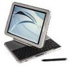
video SDRAM. The primary pointing device on the tablet PC is the tablet PC pen. Handwriting recognition software is available in Microsoft Windows XP Tablet PC Edition, the operating system installed on the tablet PC. Figure 1-1. Compaq Tablet PC TC1000 The optional keyboard is 95 percent the size - Compaq TC1000 | Maintenance and Service Guide, Compaq Tablet PC TC1000 - Page 7
Product Description The optional docking station provides access to a MultiBay and a variety of connectors. Figure 1-2. Compaq Tablet PC TC1000 with Optional Keyboard and Optional Docking Station 1-2 Maintenance and Service Guide - Compaq TC1000 | Maintenance and Service Guide, Compaq Tablet PC TC1000 - Page 8
30 GB 6 Optical drive designator W=DVD/CD-RW combination drive 0=no optical drive 7 Integrated communication 8=combination modem/NIC/wireless LAN C=combination modem/NIC 8 RAM 25=256 MB 9 Operating system T=Microsoft Windows XP Tablet Edition 10 SKU Maintenance and Service Guide 1-3 - Compaq TC1000 | Maintenance and Service Guide, Compaq Tablet PC TC1000 - Page 9
Compaq Tablet PC TC1000 Models The following Compaq Tablet PC TC1000 models use config. code LBSZ and feature: ■ Pen and PointStick keyboard ■ 6-cell, 4.0 Ah lithium ion (Li ion) battery pack ■ 16 MB of discrete video memory ■ 3-year warranty on parts 470045-255 1-4 Maintenance and Service Guide - Compaq TC1000 | Maintenance and Service Guide, Compaq Tablet PC TC1000 - Page 10
Compaq Tablet PC TC1000 models use config. code LBQZ and feature: ■ Pen and PointStick keyboard ■ 6-cell, 4.0 Ah Li ion battery pack ■ 16 MB of discrete video memory ■ 1-year warranty on parts and labor CTC1000 T 100 X0 40 W C 25 T Japan 470050-336 includes Tablet PC Docking Station CTC1000 - Compaq TC1000 | Maintenance and Service Guide, Compaq Tablet PC TC1000 - Page 11
PC TC1000 Models (Continued) The following models represent configure-to-order Compaq Tablet PC TC1000 models and use config. code LBQZ. These tablet PC models feature: ■ Pen and PointStick keyboard ■ 6-cell, 4.0 Ah Li ion battery pack ■ 16 MB of discrete video memory ■ 1-year warranty on parts - Compaq TC1000 | Maintenance and Service Guide, Compaq Tablet PC TC1000 - Page 12
Product Description Table 1-2 Compaq Tablet PC TC1000 Models (Continued) CTC1000 T 100 X0 30 0 8 76 T United States 470046-342 CTC1000 T 100 X0 30 0 8 38 T United 0 C 38 T United States 470046-347 CTC1000 T 100 X0 30 0 C 25 T United States 470046-346 Maintenance and Service Guide 1-7 - Compaq TC1000 | Maintenance and Service Guide, Compaq Tablet PC TC1000 - Page 13
pack ■ 60-, 40-, or 30-GB high-capacity SMART hard drive, varying by tablet PC model ■ Support for the following drives through the MultiBay (with optional external MultiBay or docking station): ❏ 1.44-MB diskette drive ❏ 24X Max CD-ROM drive ❏ 8X Max CD-RW drive 1-8 Maintenance and Service Guide - Compaq TC1000 | Maintenance and Service Guide, Compaq Tablet PC TC1000 - Page 14
❏ external MultiBay ❏ optional keyboard ❏ optional docking station ■ Support for the following connectors on the optional docking station: ❏ external MultiBay ❏ RJ-45 network ❏ Universal Serial Bus ❏ External monitor ❏ AC power ❏ Stereo line out/headphone Maintenance and Service Guide 1-9 - Compaq TC1000 | Maintenance and Service Guide, Compaq Tablet PC TC1000 - Page 15
"). 3. Wait approximately five minutes. 4. Replace the RTC battery and reassemble the tablet PC. Do not reinsert the battery pack at this time. 5. Connect AC power to the tablet PC. 6. Turn on the tablet PC. All passwords and all CMOS settings have been cleared. 1-10 Maintenance and Service Guide - Compaq TC1000 | Maintenance and Service Guide, Compaq Tablet PC TC1000 - Page 16
Product Description 1.4 Power Management The tablet PC comes with power management features that extend battery operating time and conserve power. The tablet PC supports the following power management features: ■ Suspend ■ Hibernation ■ Setting customization by the user ■ Hotkeys for setting level - Compaq TC1000 | Maintenance and Service Guide, Compaq Tablet PC TC1000 - Page 17
Description 1.5 Tablet PC External Components The external components on the front panel of the tablet are shown in Figure 1-3 and described in Table 1-3. Figure 1-3. Front Panel Components Table 1-3 Front Panel Components Item 1 Component Wireless LAN activity light 2 Battery light Function - Compaq TC1000 | Maintenance and Service Guide, Compaq Tablet PC TC1000 - Page 18
which supports handwriting. When the tablet PC is in Windows, opens the Microsoft Tablet PC Input Panel application, which includes a handwriting pad and an on-screen keyboard. While using the on-screen keyboard: ■ To enter the ctrl+alt+delete command, press the button on the tablet PC with the pen - Compaq TC1000 | Maintenance and Service Guide, Compaq Tablet PC TC1000 - Page 19
device. Ejects an optional PC Card from the PC Card slot. Supports an optional Type I or Type II 32-bit (CardBus) or 16-bit PC Card. Secures the pen to the tablet PC. Used with the tether eyelet on the pen, enables you to tether the pen to the tablet PC. 1-14 Maintenance and Service Guide - Compaq TC1000 | Maintenance and Service Guide, Compaq Tablet PC TC1000 - Page 20
CompactFlash card slot. Supports an optional Type I or Type II CompactFlash card. Connects an optional USB 2.0- or 1.1-compliant device. Connects a modem cable. Connects an Ethernet network cable. Both lights off: The tablet PC is not connected to a LAN. Both lights on: The tablet PC is connected to - Compaq TC1000 | Maintenance and Service Guide, Compaq Tablet PC TC1000 - Page 21
Left Side Components Table 1-5 Left Side Components Item Component 1 Security cable slot 2 Screen protector slots (2) Function Attaches an optional security cable to the tablet PC. Secure the optional screen protector when it is attached to the tablet PC. 1-16 Maintenance and Service Guide - Compaq TC1000 | Maintenance and Service Guide, Compaq Tablet PC TC1000 - Page 22
Accepts an alignment key to safeguard attachment procedures. For example, matching the alignment key on an optional tablet PC keyboard to the alignment key slot helps you correctly orient the tablet PC to the keyboard as you attach the tablet PC to the keyboard. Maintenance and Service Guide 1-17 - Compaq TC1000 | Maintenance and Service Guide, Compaq Tablet PC TC1000 - Page 23
to enter a command. ■ Rotate upward to scroll upward. ■ Rotate downward to scroll downward. While the tablet PC is: ■ Starting up and a flashing pointer is displayed on the screen, opens the Setup utility. ■ In Windows, functions like esc on a standard keyboard. 1-18 Maintenance and Service Guide - Compaq TC1000 | Maintenance and Service Guide, Compaq Tablet PC TC1000 - Page 24
command. When the tablet PC is in Windows, functions like tab on a standard keyboard. When the tablet PC is in Windows, opens or closes the Q Menu. When the tablet PC is in Windows: ■ Until your Internet or network service is set up, opens the operating system Internet connection wizard. ■ After - Compaq TC1000 | Maintenance and Service Guide, Compaq Tablet PC TC1000 - Page 25
Tablet PC Docking Station. Produce stereo sound. Connects optional stereo headphones or powered stereo speakers. Connects an optional headset, such as a mobile telephone headset with a microphone and a monaural ear piece. Connects an optional monaural microphone. 1-20 Maintenance and Service Guide - Compaq TC1000 | Maintenance and Service Guide, Compaq Tablet PC TC1000 - Page 26
used in portrait orientation as a free-standing tablet, can elevate the top of the tablet PC to provide a comfortable writing and viewing angle. Accepts the docking restraint latch on an optional docking station to secure the tablet PC to the docking station. Maintenance and Service Guide 1-21 - Compaq TC1000 | Maintenance and Service Guide, Compaq Tablet PC TC1000 - Page 27
Holds the system hard drive. 9 Pad feet (2) Stabilize the tablet PC when the tablet PC is placed as a free-standing tablet on a flat surface. 10 Battery pack Holds the battery pack. 11 Battery retention screw Secures the battery pack to the tablet PC. 1-22 Maintenance and Service Guide - Compaq TC1000 | Maintenance and Service Guide, Compaq Tablet PC TC1000 - Page 28
battery pack from the battery bay. Secure the memory and Mini PCI compartment cover to the tablet PC. Contains one memory slot for a PC133-compliant memory module. Also holds an optional Mini PCI board, such as a modem board or a combination modem and wireless board. Maintenance and Service Guide - Compaq TC1000 | Maintenance and Service Guide, Compaq Tablet PC TC1000 - Page 29
1-9. Keyboard Front Panel Components Table 1-9 Keyboard Front Panel Components Item Component 1 Alignment key 2 Keyboard hooks (2) Function Ensures the tablet PC is attached to the keyboard in the correct orientation. Secure the tablet PC to the keyboard. 1-24 Maintenance and Service Guide - Compaq TC1000 | Maintenance and Service Guide, Compaq Tablet PC TC1000 - Page 30
while it is connected to the keyboard. Help guide the tablet PC and keyboard into an optional Tablet PC Docking Station. Enables the optional docking station to be connected to the tablet PC while the keyboard is attached to the tablet PC. Moves the cursor and selects and activates items - Compaq TC1000 | Maintenance and Service Guide, Compaq Tablet PC TC1000 - Page 31
Product Description The external components on the front panel of the keyboard are shown in Figure 1-10 and described in Table 1-10. Figure 1-10. Keyboard Front Panel Components 1-26 Maintenance and Service Guide - Compaq TC1000 | Maintenance and Service Guide, Compaq Tablet PC TC1000 - Page 32
, press Fn+F11/F12. Combines with other keys to perform system tasks. For example, pressing Fn+num lk turns on the keypad. Used like an external numeric keypad. Displays the Microsoft Windows Start Menu. Displays a shortcut menu for items beneath the pointer. Maintenance and Service Guide 1-27 - Compaq TC1000 | Maintenance and Service Guide, Compaq Tablet PC TC1000 - Page 33
Product Description The components on the rear panel and bottom of the optional keyboard are shown in Figure 1-11 and described in Table 1-11. Figure 1-11. Keyboard Rear Panel and Bottom Components 1-28 Maintenance and Service Guide - Compaq TC1000 | Maintenance and Service Guide, Compaq Tablet PC TC1000 - Page 34
screen protector, from the keyboard. Secure the portfolio or optional screen protector to the keyboard. Accepts an alignment key to ensure proper orientation. Maintenance and Service Guide 1-29 - Compaq TC1000 | Maintenance and Service Guide, Compaq Tablet PC TC1000 - Page 35
Product Description 1.7 Docking Station Components The front and left side components on the optional docking station are shown in Figure 1-12 and described in Table 1-12. Figure 1-12. Docking Station Front and Left Side Components 1-30 Maintenance and Service Guide - Compaq TC1000 | Maintenance and Service Guide, Compaq Tablet PC TC1000 - Page 36
PC. Secures the tablet PC to the docking stand. Fit into the tablet PC docking alignment slots to align the tablet PC in the docking stand. Attaches an optional security cable to the tablet PC. Ejects a MultiBay device from the bay. Connects optional USB devices. Maintenance and Service Guide - Compaq TC1000 | Maintenance and Service Guide, Compaq Tablet PC TC1000 - Page 37
Product Description The rear panel and right side components on the optional docking station are shown in Figure 1-13 and described in Table 1-13. Figure 1-13. Docking Station Rear Panel and Right Side Components 1-32 Maintenance and Service Guide - Compaq TC1000 | Maintenance and Service Guide, Compaq Tablet PC TC1000 - Page 38
line-out jack 7 USB connectors (3) 8 AC power connector Function Tilts the docking stand forward and backward to enable different viewing angles and different docking modes. Supports a diskette drive, CD-ROM or CD-RW drive, DVD drive, CD-RW/DVD drive, or second hard drive. Connects a network - Compaq TC1000 | Maintenance and Service Guide, Compaq Tablet PC TC1000 - Page 39
for disassembly steps. The system board provides the following device connections: ■ Memory expansion board ■ Hard drive ■ Display ■ Optional keyboard/pointing stick ■ Audio ■ Transmeta processor ■ Fan ■ PC Card ■ CompactFlash ■ External MultiBay ■ Modem or modem/NIC The tablet PC uses an electrical - Compaq TC1000 | Maintenance and Service Guide, Compaq Tablet PC TC1000 - Page 40
The tablet PC features two Compaq system management utilities: ■ Computer Setup-A system information and customization utility that can be used even when your operating system is not working or will not load. This utility includes settings that are not available in Windows. Maintenance and Service - Compaq TC1000 | Maintenance and Service Guide, Compaq Tablet PC TC1000 - Page 41
to: ❏ Display system information. ❏ Test system components. ❏ Troubleshoot a device configuration problem in Windows 2000, Windows XP Professional, or Windows XP Home. ✎ It is not necessary to configure a device connected to a USB connector on the tablet PC or an optional docking base. Using - Compaq TC1000 | Maintenance and Service Guide, Compaq Tablet PC TC1000 - Page 42
Troubleshooting Selecting from the File Menu Table 2-1 File Menu Select System Information Save to Floppy Restore from Floppy Restore Defaults Ignore Changes and Exit Save Changes and Exit To Do This ■ View identification information about the tablet PC, a docking base, and any battery packs in - Compaq TC1000 | Maintenance and Service Guide, Compaq Tablet PC TC1000 - Page 43
Diskette write* ■ CD-ROM or diskette startup ✎ Settings for a DVD-ROM can be entered in the CD-ROM field. System IDs Enter identification numbers for the tablet PC, a docking base, and all battery packs in the system. *Not applicable to SuperDisk LS-120 drives. 2-4 Maintenance and Service Guide - Compaq TC1000 | Maintenance and Service Guide, Compaq Tablet PC TC1000 - Page 44
/disable USB legacy support for a USB keyboard. (When USB legacy support is enabled, the keyboard works even when a Windows operating system is not loaded.) ■ Set an optional external monitor or overhead projector connected to a video card in a docking base as the primary device. (When the tablet PC - Compaq TC1000 | Maintenance and Service Guide, Compaq Tablet PC TC1000 - Page 45
Enable to recognize the docking bases individually, by serial number.) ■ Enable/disable the reporting of the processor serial number by the processor to the software. HDD Self-Test Options Run a quick comprehensive self-test on hard drives in the system that support the test features. *Video - Compaq TC1000 | Maintenance and Service Guide, Compaq Tablet PC TC1000 - Page 46
Troubleshooting 2.2 Using Compaq Diagnostics When you access Compaq Diagnostics, a scan of all system components is displayed on the screen before the Compaq Diagnostics window opens. You can display more or less information from anywhere within Compaq Diagnostics by selecting Level on the menu bar. - Compaq TC1000 | Maintenance and Service Guide, Compaq Tablet PC TC1000 - Page 47
Troubleshooting Obtaining, Saving, or Printing Diagnostic Test Information 1. Access Compaq Diagnostics by selecting Start > Settings > Control Panel > Compaq Diagnostics. 2. Select the Test tab. 3. In the scroll box, the checkbox for each test you want to run. 2-8 Maintenance and Service Guide - Compaq TC1000 | Maintenance and Service Guide, Compaq Tablet PC TC1000 - Page 48
the tablet PC with their error codes. 8. Select a tab to save the report: ❏ Log tab-Select the Log tab Save button. ❏ Error tab-Select the Error tab Save button. 9. Select a tab to print the report: ❏ Log tab-Select File > Save As, then print the file from your folder. Maintenance and Service Guide - Compaq TC1000 | Maintenance and Service Guide, Compaq Tablet PC TC1000 - Page 49
3 No power, part 4 No video, part 1 No video, part 2 Nonfunctioning docking station No operating system (OS) loading No OS loading from hard drive, part 1 No OS loading from hard drive, part 2 No OS loading from hard drive, part 3 No OS loading from diskette drive No OS loading from CD- or DVD-ROM - Compaq TC1000 | Maintenance and Service Guide, Compaq Tablet PC TC1000 - Page 50
2.1-Initial Troubleshooting Begin troubleshooting. N Is there power? Y Go to Section 2.2, No Power. N Beeps, LEDs, or error messages? Y Check LED board, speaker connections. N Is there video? (no boot) Y Device. Go to Section 2.20, No Network or Modem. End Maintenance and Service Guide 2-11 - Compaq TC1000 | Maintenance and Service Guide, Compaq Tablet PC TC1000 - Page 51
Power up in docking station? *NOTES: 1. On some models there is a separate reset button. 2. On some models the tablet PC may be reset using the Suspend switch and either the lid switch or the main power switch. Go to Section 2.8, Nonfunctioning Docking Station. 2-12 Maintenance and Service Guide - Compaq TC1000 | Maintenance and Service Guide, Compaq Tablet PC TC1000 - Page 52
in battery socket and clean if necessary. Y Power on? N Done Check battery by recharging, moving it to another tablet PC, or replacing it. N Power on? Y Replace power supply (if applicable). N Done Power on? Y Go to Section 2.4, No Power, Part 3. Done Maintenance and Service Guide 2-13 - Compaq TC1000 | Maintenance and Service Guide, Compaq Tablet PC TC1000 - Page 53
Troubleshooting Flowchart 2.4-No Power, Part 3 Continued from Section 2.3, No Power, Part 2. Plug directly into AC outlet. Y Power LED on? N Reseat AC adapter in tablet PC and at power Internal Go to Section 2.5, No Power, Part 4. N Power on? Y Done Done 2-14 Maintenance and Service Guide - Compaq TC1000 | Maintenance and Service Guide, Compaq Tablet PC TC1000 - Page 54
Replace the following items (if applicable). Check tablet PC operation after each replacement: 1. Internal DC-DC converter* 2. Internal AC adapter 3. Processor board* 4. System board* *NOTE: Replace these items as a set to prevent shorting out among components. Maintenance and Service Guide 2-15 - Compaq TC1000 | Maintenance and Service Guide, Compaq Tablet PC TC1000 - Page 55
after each replacement. 1. Cable between notebook and tablet PC display (if applicable) 2. Inverter board (if applicable) 3. Display 4. System board N N Video OK? Try another display. Internal and external video OK? Replace system board. Y Y Done Done 2-16 Maintenance and Service Guide - Compaq TC1000 | Maintenance and Service Guide, Compaq Tablet PC TC1000 - Page 56
display brightness. Check brightness of external monitor. N Video OK? Y Go to "A" in Section 2.6, No Video, Part 1. Y Video OK? N Check that tablet PC is properly seated in docking station, for bent pins on cable, and for monitor connection. Y Video OK? Done N Try another external monitor - Compaq TC1000 | Maintenance and Service Guide, Compaq Tablet PC TC1000 - Page 57
into docking station. Y Docking station operating? N Done Replace the following docking station components one at a time. Check tablet PC operation after each replacement. 1. Power supply 2. I/O board 3. Backplane board 4. Switch box 5. Docking motor mechanism 2-18 Maintenance and Service Guide - Compaq TC1000 | Maintenance and Service Guide, Compaq Tablet PC TC1000 - Page 58
Flowchart 2.9-No Operating System (OS) Loading No OS Loading.* Reseat power cord in docking station and power outlet. No OS loading from hard drive, go to Section 2.10. No OS loading from diskette drive, go to Section 2.13. No OS loading from CD- or DVD-ROM drive, go to Section 2.14 - Compaq TC1000 | Maintenance and Service Guide, Compaq Tablet PC TC1000 - Page 59
Troubleshooting Flowchart 2.10-No OS Loading from Hard Drive, Part 1 OS not loading from hard drive. Y Nonsystem disk message? N Reseat external hard drive. Go to Section 2.11, No OS Loading from Hard Drive, Part 2. Y OS loading? N N Boot from CD? Y Check the setup utility for correct booting - Compaq TC1000 | Maintenance and Service Guide, Compaq Tablet PC TC1000 - Page 60
, then format hard drive to bootable C:\ prompt. Hard drive formatted? Y Format hard drive and bring to a bootable Y C:\ prompt. Tablet PC booted? N Go to Section 2.12, No OS Loading from Hard Drive, Part 3. Load OS using Restore CD (if applicable). Maintenance and Service Guide 2-21 - Compaq TC1000 | Maintenance and Service Guide, Compaq Tablet PC TC1000 - Page 61
Troubleshooting Flowchart 2.12-No OS Loading from Hard Drive, Part 3 Continued from Section 2.11, No OS Loading from Hard Drive, Part 2. N System files on hard drive? Y Install OS and reboot. Y Virus on hard drive? N Run SCANDISK and check for bad sectors. N Can bad sectors be fixed? Y Clean - Compaq TC1000 | Maintenance and Service Guide, Compaq Tablet PC TC1000 - Page 62
tablet PC. Y Check diskette for system files. Try different diskette. Y Nonsystem disk error? N 1. Replace diskette drive. 2. Replace system board. Y OS loading? N Done Change boot priority using the setup utility. Go to Section 2.17, Nonfunctioning Device. Maintenance and Service Guide - Compaq TC1000 | Maintenance and Service Guide, Compaq Tablet PC TC1000 - Page 63
Troubleshooting Flowchart 2.14-No OS Loading from CD- or DVD-ROM Drive No OS Loading from Disc CD- or in drive? DVD-ROM Drive. N Y N Bootable disc in drive? Y Install bootable disc and reboot tablet PC. Install bootable disc. Try another bootable disc. Y Boots from CD or DVD? N Done - Compaq TC1000 | Maintenance and Service Guide, Compaq Tablet PC TC1000 - Page 64
up audio internally or externally. Audio? Done N Y Tablet PC in docking station (if applicable)? N Undock N Internal audio? Go to Section 2.16, No Audio, Part 2. Y Go to Section 2.16, No Audio, Part 2. Replace the following docking station components one at a time as applicable. Check - Compaq TC1000 | Maintenance and Service Guide, Compaq Tablet PC TC1000 - Page 65
drivers and set configuration in OS. Connect to external speaker. N Audio? Y Replace audio board and speaker connections in tablet PC (if applicable). Y Audio? N Done 1. Replace internal speakers. 2. Replace audio board (if applicable). 3. Replace system board. 2-26 Maintenance and Service - Compaq TC1000 | Maintenance and Service Guide, Compaq Tablet PC TC1000 - Page 66
Reattach device. Close tablet PC, plug in power, and reboot. N Device boots properly? Y Done Y Any physical device detected? N Possible bad hard drive. Replace drive. Possible bad NIC. Replace card. If integrated NIC, replace system board. Possible bad diskette drive. Replace drive. Fix or replace - Compaq TC1000 | Maintenance and Service Guide, Compaq Tablet PC TC1000 - Page 67
operating properly. Connect tablet PC to good external keyboard. N External device works? Y Replace system board. Reseat internal keyboard connector (if applicable). N OK? Y Replace internal keyboard or cable. Y Done OK? N Replace system board. Done 2-28 Maintenance and Service Guide - Compaq TC1000 | Maintenance and Service Guide, Compaq Tablet PC TC1000 - Page 68
Troubleshooting Flowchart 2.19-Nonfunctioning Pointing Device Pointing device not operating properly. Connect tablet PC to good external pointing device. N External device works? Y Replace system board. Reseat internal pointing device connector (if applicable). N Replace internal OK? - Compaq TC1000 | Maintenance and Service Guide, Compaq Tablet PC TC1000 - Page 69
jack or have jack activated. Connect to nondigital line. Reload drivers and reconfigure. Disconnect all power from the tablet PC and open. Reseat NIC/modem (if applicable). Y OK? N Replace NIC/modem (if applicable). Y OK? N Done Done Replace system board. 2-30 Maintenance and Service Guide - Compaq TC1000 | Maintenance and Service Guide, Compaq Tablet PC TC1000 - Page 70
for spare part numbers and option part numbers. 3.1 Serial Number Location When ordering parts or requesting information, provide the tablet PC serial number and model number located on the bottom of the tablet PC (Figure 3-1). Figure 3-1. Serial Number Location Maintenance and Service Guide 3-1 - Compaq TC1000 | Maintenance and Service Guide, Compaq Tablet PC TC1000 - Page 71
Illustrated Parts Catalog 3.2 Tablet PC System Major Components Figure 3-2. Tablet PC Major Components 3-2 Maintenance and Service Guide - Compaq TC1000 | Maintenance and Service Guide, Compaq Tablet PC TC1000 - Page 72
Keyboard release assembly Pen holder Pen holder push block assembly Mini PCI communications/memory expansion compartment cover Hard drive cover not illustrated: tablet PC feet Spare Part Number 311062-001 310667-001 310676-001 310666-001 310673-001 310678-001 Maintenance and Service Guide 3-3 - Compaq TC1000 | Maintenance and Service Guide, Compaq Tablet PC TC1000 - Page 73
Illustrated Parts Catalog Figure 3-2. Tablet PC Major Components 3-4 Maintenance and Service Guide - Compaq TC1000 | Maintenance and Service Guide, Compaq Tablet PC TC1000 - Page 74
, LED board assembly, connector cover, and shields) Wireless local area network (LAN) board (mini PCI, Type III) Memory expansion board (DDR, 256 MB) Battery pack, Li ion Real time clock (RTC) battery Hard drives 40 GB 30 GB Spare Part Number 310664-001 310665-001 310672-001 310679-001 310671 - Compaq TC1000 | Maintenance and Service Guide, Compaq Tablet PC TC1000 - Page 75
Figure 3-3. Miscellaneous Cable Kit Components Table 3-2 Miscellaneous Cable Kit Components Spare Part Number 310673-001 Item 1 2 3 4 5 6 Description Modem cable Display panel cable Speaker cable Digitizer cable Display inverter cable Switch board cable 3-6 Maintenance and Service Guide - Compaq TC1000 | Maintenance and Service Guide, Compaq Tablet PC TC1000 - Page 76
-001 Item 1 2 3 4 5 6 7 8 Description CompactFlash card slot space saver PC Card slot space saver Pen holder push block assembly Pen holder Tablet PC feet (2) Hard drive cover Keyboard release assembly Memory expansion/mini PCI communications compartment cover Maintenance and Service Guide 3-7 - Compaq TC1000 | Maintenance and Service Guide, Compaq Tablet PC TC1000 - Page 77
Parts Catalog 3.5 Keyboard Figure 3-5. Tablet PC TC1000 Keyboard Table 3-4 Tablet PC TC1000 Keyboard Description Tablet PC TC1000 of China Sweden/Finland Switzerland Taiwan United Kingdom United States Spare Part Number 310681-AD1 310681-091 310681-AA1 310681-101 310681-111 310681-AB1 - Compaq TC1000 | Maintenance and Service Guide, Compaq Tablet PC TC1000 - Page 78
3.6 Docking Station Illustrated Parts Catalog Figure 3-6. Compaq Tablet PC TC1000 Docking Station Table 3-5 Optional Docking Station Description Tablet PC TC1000 Docking Station Spare Part Number 311063-001 Maintenance and Service Guide 3-9 - Compaq TC1000 | Maintenance and Service Guide, Compaq Tablet PC TC1000 - Page 79
Illustrated Parts Catalog 3.7 Docking Station Components Figure 3-7. Compaq Tablet PC TC1000 Docking Station Components 3-10 Maintenance and Service Guide - Compaq TC1000 | Maintenance and Service Guide, Compaq Tablet PC TC1000 - Page 80
Illustrated Parts Catalog Table 3-6 Docking Station Components Item 1 2 3 4 Description Docking stand and pivot arm Top case Board assembly Bottom case Spare Part Number 311189-001 311190-001 311192-001 311191-001 Maintenance and Service Guide 3-11 - Compaq TC1000 | Maintenance and Service Guide, Compaq Tablet PC TC1000 - Page 81
Pen (uses a 1.5 VDC, AAAA battery) Tablet PC Miscellaneous Screw Kit (includes the following screws; refer to Appendix C, "Screw Listing," for more information on screw specifications and usage.) ■ Phillips M2.0 × 4.0 ■ Phillips M2.0 × 5.0 ■ Phillips M2.0 × 3.5 ■ Torx M2.5 × 7.0 Docking Station - Compaq TC1000 | Maintenance and Service Guide, Compaq Tablet PC TC1000 - Page 82
Preliminaries This chapter provides essential information for proper and safe removal and replacement service. 4.1 Tools Required You will need the following tools to complete the removal kit (includes connector removal tool, loopback plugs, and case utility tool) Maintenance and Service Guide 4-1 - Compaq TC1000 | Maintenance and Service Guide, Compaq Tablet PC TC1000 - Page 83
are routed in such a way that they cannot be caught or snagged by parts being removed or replaced. Handle flex cables with extreme care; these cables tear easily. Ä CAUTION: When servicing the tablet PC, ensure that cables are placed in their proper locations during the reassembly process. Improper - Compaq TC1000 | Maintenance and Service Guide, Compaq Tablet PC TC1000 - Page 84
the following precautions: ■ Before removing or inserting a hard drive, shut down the tablet PC. If you are unsure whether the tablet PC is off or in Hibernation, turn on the tablet PC, then shut it down. ■ Before removing a diskette drive or optical drive, ensure that a diskette or disc is not in - Compaq TC1000 | Maintenance and Service Guide, Compaq Tablet PC TC1000 - Page 85
electrostatic-sensitive parts in their containers until the parts arrive at static-free workstations. ■ Place items on a grounded surface before removing items from their containers. ■ Always be properly grounded when touching a sensitive component or assembly. 4-4 Maintenance and Service Guide - Compaq TC1000 | Maintenance and Service Guide, Compaq Tablet PC TC1000 - Page 86
components, parts, and assemblies by the case or PCM laminate. Handle these items only at static-free workstations. ■ Avoid contact with pins, leads, or circuitry. ■ Turn off power and input signals before inserting or removing connectors or test equipment. Maintenance and Service Guide 4-5 - Compaq TC1000 | Maintenance and Service Guide, Compaq Tablet PC TC1000 - Page 87
system. boot straps) can be used at standing workstations and are compatible with most types of shoes or boots . On conductive floors or dissipative floor mats, use foot straps on both feet with a minimum of one-megohm resistance between the operator hard ties to the ground ■ Field service - Compaq TC1000 | Maintenance and Service Guide, Compaq Tablet PC TC1000 - Page 88
4-2 Static-Shielding Materials Material Antistatic plastic Carbon-loaded plastic Metallized laminate Use Bags Floor mats Floor mats Voltage Protection Level 1,500 V 7,500 V 5,000 V Maintenance and Service Guide 4-7 - Compaq TC1000 | Maintenance and Service Guide, Compaq Tablet PC TC1000 - Page 89
. Torx T8 and Phillips P0 screws are removed during the disassembly of the tablet PC and the docking station. There are 36 screws, in 4 different sizes, that must be removed, replaced, and loosened when servicing the tablet PC. There are 17 screws, in 4 different sizes, that must be removed and - Compaq TC1000 | Maintenance and Service Guide, Compaq Tablet PC TC1000 - Page 90
Removal and Replacement Procedures 5.1 Serial Number Report the tablet PC serial number to Compaq when requesting information or ordering spare parts. The serial number is located on the bottom of the tablet PC (Figure 5-1). Figure 5-1. Serial Number Location 5-2 Maintenance and Service Guide - Compaq TC1000 | Maintenance and Service Guide, Compaq Tablet PC TC1000 - Page 91
Description Preparing the tablet PC for disassembly Battery pack Mini PCI communications board Memory expansion board Hard drive Real time clock (RTC) battery Display panel assembly Speaker assembly Digitizer cable System board Fan and heat sink Modem cable Switch board Docking station Number of - Compaq TC1000 | Maintenance and Service Guide, Compaq Tablet PC TC1000 - Page 92
the AC adapter and all external devices. 3. Remove the battery pack by following these steps: Battery Pack Spare Part Number Information Battery pack, Li ion 302119-001 a. Turn the tablet panel side down with the power switch and jog dial facing you. 5-4 Maintenance and Service Guide - Compaq TC1000 | Maintenance and Service Guide, Compaq Tablet PC TC1000 - Page 93
b. Remove the PM2.0 × 4.0 screw 1 that secures the battery pack to the tablet PC (Figure 5-2). c. Slide the battery release latch 2 toward the back of the tablet to release the battery pack. d. Use the notch in the battery pack to lift the left side of the battery pack up and swing it to the right - Compaq TC1000 | Maintenance and Service Guide, Compaq Tablet PC TC1000 - Page 94
facing you. b. Remove the two PM2.0 × 4.0 screws 1 that secure the mini PCI communications/memory expansion slot cover to the tablet PC (Figure 5-3). c. Lift the back edge of the mini PCI communications/ memory expansion slot cover up and swing it forward 2. d. Remove the mini PCI communications - Compaq TC1000 | Maintenance and Service Guide, Compaq Tablet PC TC1000 - Page 95
the mini PCI communications board to the system board. g. The mini PCI communications board Part Number Information Mini PCI Type III wireless local area network (LAN) card 310670-001 Reverse the preceding procedures to install the mini PCI communications board. Maintenance and Service Guide - Compaq TC1000 | Maintenance and Service Guide, Compaq Tablet PC TC1000 - Page 96
the connector at a 45-degree angle 2. Figure 5-5. Removing the Memory Expansion Board Memory Expansion Board Spare Part Number Information 256 MB DDR memory expansion board 310677-001 Reverse the preceding procedures to install the memory expansion board. 5-8 Maintenance and Service Guide - Compaq TC1000 | Maintenance and Service Guide, Compaq Tablet PC TC1000 - Page 97
tablet PC (Figure 5-6). c. Lift the front edge of the cover up and swing the cover back 2. d. Remove the hard drive cover. ✎ The hard drive cover is included in the Miscellaneous Plastics/Hardware kit, spare part number 310678-001. Figure 5-6. Removing the Hard Drive Cover Maintenance and Service - Compaq TC1000 | Maintenance and Service Guide, Compaq Tablet PC TC1000 - Page 98
it from the system board (Figure 5-7). f. Remove the hard drive from the tablet 3. Figure 5-7. Removing the Hard Drive Reverse the preceding procedures to install the hard drive. Hard Drive Spare Part Number Information 40 GB 30 GB 311240-001 310668-001 5-10 Maintenance and Service Guide - Compaq TC1000 | Maintenance and Service Guide, Compaq Tablet PC TC1000 - Page 99
(RTC) Battery RTC Battery Spare Part Number Information Disk cell RTC battery 310675-001 Perform the following steps to remove the RTC battery: 1. Prepare the tablet PC for disassembly (Section 5.3). 2. Remove the mini PCI communications/memory expansion slot cover. 3. Turn the tablet PC panel - Compaq TC1000 | Maintenance and Service Guide, Compaq Tablet PC TC1000 - Page 100
Assembly Components Spare Part Number Information Display panel assembly Display bezel with inverter Bridge battery Digitizer 311062-001 310667-001 310676-001 310666-001 Perform the following steps to remove and disassemble the display panel assembly: 1. Prepare the tablet PC for disassembly - Compaq TC1000 | Maintenance and Service Guide, Compaq Tablet PC TC1000 - Page 101
× 7.0 screws 1 that secure the display panel assembly to the tablet PC (Figure 5-9). 4. Open the bottom tilt foot 2 and remove the TM2.5 × 7.0 screw 3 that secures the display panel assembly to the tablet PC. Figure 5-9. Removing the Display Panel Assembly Screws Maintenance and Service Guide 5-13 - Compaq TC1000 | Maintenance and Service Guide, Compaq Tablet PC TC1000 - Page 102
(Figure 5-10). 6. Remove the TM2.5 × 7.0 screw 2 that secures the display panel assembly to the tablet PC. 7. Disconnect the digitizer cable 3 in the hard drive bay. Figure 5-10. Removing the Display Panel Assembly Screw and Disconnecting the Digitizer Cable 5-14 Maintenance and Service Guide - Compaq TC1000 | Maintenance and Service Guide, Compaq Tablet PC TC1000 - Page 103
Removal and Replacement Procedures 8. Turn the tablet PC panel side up with the power switch and jog dial facing you. 9. Lift and hold the front edge of straight up 4 to remove it from the display panel assembly. Figure 5-11. Removing the Display Panel Assembly Maintenance and Service Guide 5-15 - Compaq TC1000 | Maintenance and Service Guide, Compaq Tablet PC TC1000 - Page 104
Removal and Replacement Procedures 12. Position the display panel assembly so the display panel is facing down and the inverter and bridge battery are facing you. 13. Remove the two PM2.0 × 5.0 screws 1 that secure the display panel bracket to the display panel assembly (Figure 5-12). 14. Remove the - Compaq TC1000 | Maintenance and Service Guide, Compaq Tablet PC TC1000 - Page 105
. Remove the tape 4 that secures the inverter board cable to the back of the display panel. Figure 5-13. Disconnecting the Display Panel Cables Maintenance and Service Guide 5-17 - Compaq TC1000 | Maintenance and Service Guide, Compaq Tablet PC TC1000 - Page 106
edge of the display panel 3 and slide it forward 4 to remove it from the display bezel. Figure 5-14. Removing the Display Panel 5-18 Maintenance and Service Guide - Compaq TC1000 | Maintenance and Service Guide, Compaq Tablet PC TC1000 - Page 107
Removal and Replacement Procedures 21. Remove the PM2.0 × 5.0 screw 1 that secures the digitizer to the display panel assembly (Figure 5-15). 22. Lift the front edge of the digitizer 2 and slide it out 3 of the display panel. Figure 5-15. Removing the Digitizer Maintenance and Service Guide 5-19 - Compaq TC1000 | Maintenance and Service Guide, Compaq Tablet PC TC1000 - Page 108
the bridge battery cable 1 from the panel inverter board (Figure 5-16). 24. Remove the bridge battery 2 from the panel bezel. Figure 5-16. Removing the Bridge Battery Reverse the preceding procedures to reassemble and install the display panel assembly. 5-20 Maintenance and Service Guide - Compaq TC1000 | Maintenance and Service Guide, Compaq Tablet PC TC1000 - Page 109
Assembly Spare Part Number Information Speaker assembly and audio board 310679-001 Perform the following steps to remove the speaker assembly: 1. Prepare the tablet PC for disassembly 3 from the base enclosure. Figure 5-17. Removing the Speaker Assembly Maintenance and Service Guide 5-21 - Compaq TC1000 | Maintenance and Service Guide, Compaq Tablet PC TC1000 - Page 110
cable to the PC Card assembly. 8. Remove the speaker cable 4. ✎ The speaker cable is included in the Miscellaneous Cable Kit, spare part number 310673-001. Figure 5-18. Removing the Speaker Cable Reverse the preceding procedures to install the speaker assembly. 5-22 Maintenance and Service Guide - Compaq TC1000 | Maintenance and Service Guide, Compaq Tablet PC TC1000 - Page 111
spare part number 310673-001. Perform the following steps to remove the digitizer cable: 1. Prepare the tablet PC for disassembly (Section 5.3). 2. Remove the display panel assembly (Section 5.5). 3. Disconnect the digitizer cable 1 from the system board (Figure 5-19). 4. Remove the digitizer cable - Compaq TC1000 | Maintenance and Service Guide, Compaq Tablet PC TC1000 - Page 112
Part Number Information System board with fan and heat sink (includes 256 MB memory) 310664-001 Perform the following steps to remove the system board: 1. Prepare the tablet PC for disassembly (Section 5.3). 2. Remove the display panel assembly (Section 5.5). 5-24 Maintenance and Service Guide - Compaq TC1000 | Maintenance and Service Guide, Compaq Tablet PC TC1000 - Page 113
Removal and Replacement Procedures 3. Position the tablet PC base enclosure so the heat sink grille faces you. 4. Remove the four TM2.5 × 7.0 screws 1 that the Miscellaneous Plastics/Hardware kit, 310678-001. Figure 5-20. Removing the Keyboard Release Assembly Maintenance and Service Guide 5-25 - Compaq TC1000 | Maintenance and Service Guide, Compaq Tablet PC TC1000 - Page 114
. After this tab is positioned properly, install the keyboard release assembly 2 and screws 3 (Figure 5-21). Figure 5-21. Installing the Keyboard Release Assembly 5-26 Maintenance and Service Guide - Compaq TC1000 | Maintenance and Service Guide, Compaq Tablet PC TC1000 - Page 115
slot device 4 from the card slot. ✎ The PC Card slot space saver 2 and CompactFlash slot space saver 4 are included in the Miscellaneous Plastics/Hardware kit, spare part number 310678-001. Figure 5-22. Removing the PC Card and CompactFlash Card Slot Devices Maintenance and Service Guide 5-27 - Compaq TC1000 | Maintenance and Service Guide, Compaq Tablet PC TC1000 - Page 116
to which the switch board cable is attached and disconnect the cable 2 from the system board (Figure 5-23). 12. Release the ZIF connector 3 to which the switch Miscellaneous Cable Kit, spare part number 310673-001. Figure 5-23. Removing the Switch Board Cable 5-28 Maintenance and Service Guide - Compaq TC1000 | Maintenance and Service Guide, Compaq Tablet PC TC1000 - Page 117
screws are located in the following locations: ❏ Next to the pen holder spring clip 3 ❏ Directly behind the USB connectors 4 ❏ Directly behind the external monitor connector 5 ❏ Left side of the heat sink grille 6 Figure 5-24. Removing the System Board Screws Maintenance and Service Guide 5-29 - Compaq TC1000 | Maintenance and Service Guide, Compaq Tablet PC TC1000 - Page 118
side of the system board 2 until it rests at a 45-degree angle (Figure 5-25). 17. Slide the system board away from the base enclosure at an angle 3 to remove it. Figure 5-25. Removing the System Board Reverse the preceding procedures to install the system board. 5-30 Maintenance and Service Guide - Compaq TC1000 | Maintenance and Service Guide, Compaq Tablet PC TC1000 - Page 119
also be ordered using spare part number 310665-001. Perform the following steps to remove the fan and heat sink: 1. Prepare the tablet PC for disassembly (Section 5.3). 2. Remove the display panel assembly (Section 5.5). 3. Remove the system board (Section 5.8). Maintenance and Service Guide 5-31 - Compaq TC1000 | Maintenance and Service Guide, Compaq Tablet PC TC1000 - Page 120
Removal and Replacement Procedures 4. Remove the three PM2.0 × 3.5 screws 1 that secure the EMI shield to the base enclosure (Figure 5-26). 5. Remove the shield 2. 6. Disconnect the fan cable 3 from the system board. Figure 5-26. Removing the EMI Shield 5-32 Maintenance and Service Guide - Compaq TC1000 | Maintenance and Service Guide, Compaq Tablet PC TC1000 - Page 121
board shield 1 (Figure 5-27). 9. Remove the three PM2.0 × 5.0 screws 2 that secure the fan and heat sink to the system board. 10. Lift the system board straight up 3. The fan and heat sink 4 will remain resting on the work surface. Figure 5-27. Removing the Fan and Heat Sink Reverse the - Compaq TC1000 | Maintenance and Service Guide, Compaq Tablet PC TC1000 - Page 122
Cable Kit, spare part number 310673-001. Perform the following steps to remove the modem cable: 1. Prepare the tablet PC for disassembly (Section 5.3). 2. Remove the display panel assembly (Section 5.5). 3. Remove the system board (Section 5.8). 4. Position the system board with the fan - Compaq TC1000 | Maintenance and Service Guide, Compaq Tablet PC TC1000 - Page 123
steps to remove the switch board: 1. Prepare the tablet PC for disassembly (Section 5.3). 2. Remove the display panel assembly (Section 5.5). 3. Remove the system board (Section 5.8). 4. Position the tablet PC base enclosure so the PC Card slot faces you. Maintenance and Service Guide 5-35 - Compaq TC1000 | Maintenance and Service Guide, Compaq Tablet PC TC1000 - Page 124
Removal and Replacement Procedures 5. Route the wireless LAN antenna cable 1 out of the clips in the pen holder (Figure 5-29). 6. Remove the PM2.0 × 3.5 screw 2 that secures the switch board to the base enclosure. 7. Remove the switch board 3. Figure 5-29. Removing the Switch - Compaq TC1000 | Maintenance and Service Guide, Compaq Tablet PC TC1000 - Page 125
docking station: 1. Position the docking station bottom side up, resting on the docking stand, with the bottom case facing you. 2. Remove the four TM2.5 × 7.0 screws that secure the top case to the bottom case (Figure 5-30). Figure 5-30. Removing the Top Case Screws Maintenance and Service Guide - Compaq TC1000 | Maintenance and Service Guide, Compaq Tablet PC TC1000 - Page 126
with the rear panel facing you and the docking stand swung all the way back. 4. Lift the left rear edge of the top case 1 until the rear edge of the case 2 disengages from the bottom case (Figure 5-31). 5. Remove the top case 3. Figure 5-31. Removing the Top Case 5-38 Maintenance and Service Guide - Compaq TC1000 | Maintenance and Service Guide, Compaq Tablet PC TC1000 - Page 127
Removal and Replacement Procedures 6. Disconnect the docking stand cable 1 from the board assembly 2 (Figure 5-32). Figure 5-32. Disconnecting the Docking Stand Cable Maintenance and Service Guide 5-39 - Compaq TC1000 | Maintenance and Service Guide, Compaq Tablet PC TC1000 - Page 128
sure the docking stand and pivot arm are supported before removing the following screws. The docking stand and pivot arm can fall if not supported. 7. bottom case 8. Remove the docking stand and pivot arm 4. Figure 5-33. Removing the Docking Stand and Pivot Arm 5-40 Maintenance and Service Guide - Compaq TC1000 | Maintenance and Service Guide, Compaq Tablet PC TC1000 - Page 129
Removal and Replacement Procedures 9. Disconnect the switch cable 1 from the board assembly (Figure 5-34). 10. Remove the seven PM2.5 × 5.0 screws 2 that secure the board assembly to the bottom case. Figure 5-34. Removing the Board Assembly Screws Maintenance and Service Guide 5-41 - Compaq TC1000 | Maintenance and Service Guide, Compaq Tablet PC TC1000 - Page 130
the board assembly straight up 3 to remove it from the bottom case. Figure 5-35. Removing the Board Assembly Reverse the preceding procedures to assemble the docking station. 5-42 Maintenance and Service Guide - Compaq TC1000 | Maintenance and Service Guide, Compaq Tablet PC TC1000 - Page 131
specifications. Table 6-1 Tablet PC Dimensions Height Width Depth 27.4 cm 21.6 cm 2.0 cm 10.8 in 8.5 in .8 in Weight (varies by configuration) Tablet PC only Tablet PC with keyboard 1.4 kg 1.8 kg 3.1 lb 4.0 lb Stand-alone power requirements Nominal operating voltage Maximum operating - Compaq TC1000 | Maintenance and Service Guide, Compaq Tablet PC TC1000 - Page 132
/min sweep rate 1.0 G zero-to-peak, 10 to 500 Hz, 0.5 oct/min sweep rate ✎ Applicable product safety standards specify thermal limits for plastic surfaces. The tablet PC operates well within this range of temperatures. 6-2 Maintenance and Service Guide - Compaq TC1000 | Maintenance and Service Guide, Compaq Tablet PC TC1000 - Page 133
Specifications Table 6-2 10.4-inch XGA, TFT Display Dimensions Height Width Diagonal Number of colors Contrast ratio Brightness Pixel resolution Pitch Format 0.264 × 0.264 mm 1024 × 768 RGB vertical stripe Edge lit 80 × 25 3.75 W 9.29 in 6.81 in 10.4 in Maintenance and Service Guide 6-3 - Compaq TC1000 | Maintenance and Service Guide, Compaq Tablet PC TC1000 - Page 134
Specifications Table 6-3 Hard Drives User capacity per drive1 60 GB 60.0 GB Drive height 9.5 mm Drive width 70 mm drive specifications may differ slightly. Certain restrictions and exclusions apply. Consult the Compaq Customer Support Center for details. 6-4 Maintenance and Service Guide - Compaq TC1000 | Maintenance and Service Guide, Compaq Tablet PC TC1000 - Page 135
Specifications Table 6-3 Hard Drives (Continued) 60 GB 30 GB Physical 2System capability may differ. 3Actual drive specifications may differ slightly. Certain restrictions and exclusions apply. Consult the Compaq Customer Support Center for details. Maintenance and Service Guide 6-5 - Compaq TC1000 | Maintenance and Service Guide, Compaq Tablet PC TC1000 - Page 136
Specifications Table 6-4 Diskette Drive (For Use Only in the Docking Station or External MultiBay) Diskette size Light high/low) Settling time Latency average 3.5 inch On system 0.5 in (12.7 mm) 512 18 (1.44 MB) 9 80 80 2 3 to 6 ms 95 to 174 ms 15 ms 100 ms 6-6 Maintenance and Service Guide - Compaq TC1000 | Maintenance and Service Guide, Compaq Tablet PC TC1000 - Page 137
Specifications Table 6-5 CD-ROM Drive (For Use Only in the Docking Station or External MultiBay) Applicable disk Center hole diameter Disk diameter Disk thickness Track pitch Access time Random Full stroke Cache buffer Data transfer rate Sustained, - Compaq TC1000 | Maintenance and Service Guide, Compaq Tablet PC TC1000 - Page 138
Specifications Table 6-6 DVD-ROM Drive (For Use Only in the Docking Station or External MultiBay) Applicable disk Center hole diameter Disk diameter Disk thickness Track pitch Access time Random Full stroke Audio output level Cache buffer Data transfer rate Max 24X CD Max 8X DVD Normal IO Mode 4 ( - Compaq TC1000 | Maintenance and Service Guide, Compaq Tablet PC TC1000 - Page 139
Specifications Table 6-7 CD-RW Drive (For Use Only in the Docking Station or External MultiBay) Center hole diameter Disk diameter Disk thickness Track pitch Access time Random Full stroke Audio output level Cache buffer Data transfer rate Sustained, 16X Sustained, 4X CD-RW Normal PIO Mode 4 ( - Compaq TC1000 | Maintenance and Service Guide, Compaq Tablet PC TC1000 - Page 140
Nonoperating Battery recharge time System off or in Standby System on (varies depending on system power consumption) 0.30 kg 11.1 V 3.6 Ah 40.0 Wh 0 to 40° C -10 to 50° C -20 to 60° C 2.5 hours 3 to 6 hours 0.65 lb 32 to 104° F 14 to 122° F -4 to 140° F 6-10 Maintenance and Service Guide - Compaq TC1000 | Maintenance and Service Guide, Compaq Tablet PC TC1000 - Page 141
, DMA3, none) DMA2 Diskette drive DMA3 ECP parallel port LPT1 (default; alternate=DMA0, none) DMA4 DMA controller cascading (not available) DMA5 Available for PC Card DMA6 Not assigned DMA7 Not assigned ✎ PC Card controller can use DMA 1, 2, or 5. Maintenance and Service Guide 6-11 - Compaq TC1000 | Maintenance and Service Guide, Compaq Tablet PC TC1000 - Page 142
drive) IRQ15 System use ✎ PC Cards may assert IRQ3, IRQ4, IRQ5, IRQ7, IRQ9, IRQ10, IRQ11, or IRQ15. Either the infrared or the serial port may assert IRQ3 or IRQ4. *Default configuration; audio possible configurations are IRQ5, IRQ7, IRQ9, IRQ10, or none. 6-12 Maintenance and Service Guide - Compaq TC1000 | Maintenance and Service Guide, Compaq Tablet PC TC1000 - Page 143
Specifications Table 6-12 System I/O Addresses I/O Address (hex) 000 - 00F 010 - 01F 020 - 021 022 - 024 025 - 03F 02E - 02F 040 - 05F 044 - 05F 060 061 062 - 063 064 065 - 06F 070 - 071 072 - 07F 080 - 08F 090 - 091 092 093 - 09F 0A0 - 0A1 System no. 2 Maintenance and Service Guide 6-13 - Compaq TC1000 | Maintenance and Service Guide, Compaq Tablet PC TC1000 - Page 144
Specifications Table 6-12 System I/O Addresses (Continued) I/O Address (hex) 0A2 - 0BF 0C0 - 0DF 0E0 - 0EF 0F0 - 0F1 0F2 - 0FF 100 - 16F 170 - 177 178 - 1EF 1F0 - 1F7 1F8 - 200 201 202 - 21F 220 - 22F 230 - 26D 26E - 26 278 - 27F 280 - 2AB 2A0 - 2A7 2A8 - 2E7 2E8 - 2EF System and Service Guide - Compaq TC1000 | Maintenance and Service Guide, Compaq Tablet PC TC1000 - Page 145
FM synthesizer-OPL3 Unused VGA Reserved (parallel port/no EPP support) VGA PC Card controller in CPU Unused Internal modem "A" diskette controller Serial port (COM1/default) PCI configuration index register (PCIDIVO-1) PCI configuration data register (PCIDIVO-1) Maintenance and Service Guide 6-15 - Compaq TC1000 | Maintenance and Service Guide, Compaq Tablet PC TC1000 - Page 146
00FFFFFF 01000000-047FFFFF 04800000-07FFFFFF 08000000-080FFFFF 08200000-FFFEFFFF FFFF0000-FFFFFFFF System Function Base memory Video memory Video BIOS Unused System BIOS Extended memory Super extended memory Unused Video memory (direct access) Unused System BIOS 6-16 Maintenance and Service Guide - Compaq TC1000 | Maintenance and Service Guide, Compaq Tablet PC TC1000 - Page 147
A Connector Pin Assignments Table A-1 RJ-45 Network Interface Pin Signal 1 Transmit + 2 Transmit - 3 Receive + 4 Unused Pin Signal 5 Unused 6 Receive - 7 Unused 8 Unused Maintenance and Service Guide A-1 - Compaq TC1000 | Maintenance and Service Guide, Compaq Tablet PC TC1000 - Page 148
Connector Pin Assignments Table A-2 RJ-11 Modem Pin Signal 1 Unused 2 Tip 3 Ring Pin Signal 4 Unused 5 Unused 6 Unused Table A-3 Universal Serial Bus Pin Signal 1 +5 VDC 2 Data - A-2 Pin Signal 3 Data + 4 Ground Maintenance and Service Guide - Compaq TC1000 | Maintenance and Service Guide, Compaq Tablet PC TC1000 - Page 149
analog Pin Signal 9 +5 VDC 10 Ground 11 Monitor detect 12 DDC 2B data 13 Horizontal sync 14 Vertical sync 15 DDC 2B clock Maintenance and Service Guide A-3 - Compaq TC1000 | Maintenance and Service Guide, Compaq Tablet PC TC1000 - Page 150
Connector Pin Assignments Table A-5 Stereo Speaker/Headphone Pin Signal 1 Audio out Pin Signal 2 Ground Table A-6 Microphone Pin Signal 1 Audio in Pin Signal 2 Ground A-4 Maintenance and Service Guide - Compaq TC1000 | Maintenance and Service Guide, Compaq Tablet PC TC1000 - Page 151
voltage rating of 125 or 250 volts AC, as required by each country's power system. ■ The appliance coupler must meet the mechanical configuration of an EN 60 320/IEC 320 Standard Sheet C13 connector for mating with the appliance inlet on the back of the tablet PC. Maintenance and Service Guide B-1 - Compaq TC1000 | Maintenance and Service Guide, Compaq Tablet PC TC1000 - Page 152
Power Cord Set Requirements Country-Specific Requirements 3-Conductor Power Cord Set Requirements Country Australia Austria Belgium Canada Denmark Finland France VDE IMQ METI KEMA NEMKO SEMKO SEV BSI UL Applicable Note Number 1 1 1 2 1 1 1 1 1 3 1 1 1 1 1 2 B-2 Maintenance and Service Guide - Compaq TC1000 | Maintenance and Service Guide, Compaq Tablet PC TC1000 - Page 153
or VCTF, 3-conductor, 1.00 mm2 conductor size. The wall plug must be a two-pole grounding type with a Japanese Industrial Standard C8303 (7 A, 125 V) configuration. Maintenance and Service Guide B-3 - Compaq TC1000 | Maintenance and Service Guide, Compaq Tablet PC TC1000 - Page 154
tablet PC and the docking station. All screws listed in this appendix are available for the tablet PC in the Miscellaneous Screw Kit, spare part number 310674-001, and for the docking station in the Miscellaneous Docking Station Screw Kit, spare part number 311241-001. Maintenance and Service Guide - Compaq TC1000 | Maintenance and Service Guide, Compaq Tablet PC TC1000 - Page 155
1 One screw that secures the battery pack to the tablet PC (documented in Section 5.3) 2 Two screws that secure the mini PCI communications/memory expansion slot cover to the tablet PC (documented in Section 5.3) 3 Two screws that secure the hard drive bracket to the tablet PC (documented in Section - Compaq TC1000 | Maintenance and Service Guide, Compaq Tablet PC TC1000 - Page 156
used: Four screws that secure the display panel to the display bezel (documented in Section 5.5) Head Width 4.0 mm Figure C-2. Phillips M2.0 × 4.0 Screw Locations Maintenance and Service Guide C-3 - Compaq TC1000 | Maintenance and Service Guide, Compaq Tablet PC TC1000 - Page 157
: 1 One screw that secures the connector cover and display panel assembly to the tablet PC (documented in Section 5.5) 2 Eight screws that secure the display panel assembly to the tablet PC (documented in Section 5.5) Figure C-3. Torx M2.5 × 7.0 Screw Locations C-4 Maintenance and Service Guide - Compaq TC1000 | Maintenance and Service Guide, Compaq Tablet PC TC1000 - Page 158
4.0 mm Where used: Four screws that secure the keyboard release assembly to the base enclosure (documented in Section 5.8) Figure C-4. Torx M2.5 × 7.0 Screw Locations Maintenance and Service Guide C-5 - Compaq TC1000 | Maintenance and Service Guide, Compaq Tablet PC TC1000 - Page 159
M2.5 × 7.0 Screw (Continued) Head mm Color Qty. Length Thread Width Silver 17 7.0 mm 2.5 mm 4.0 mm Where used: Four screws that secure the docking station top case to the bottom case (documented in Section 5.12) Figure C-5. Torx M2.5 × 7.0 Screw Locations C-6 Maintenance and Service Guide - Compaq TC1000 | Maintenance and Service Guide, Compaq Tablet PC TC1000 - Page 160
2.0 mm 4.0 mm Where used: 1 Two screws that secure the display panel bracket to the display panel assembly (documented in Section 5.5) 2 One screw that secures the digitizer to the display panel assembly (documented in Section 5.5) Figure C-6. Phillips M2.0 × 5.0 Screw Locations Maintenance and - Compaq TC1000 | Maintenance and Service Guide, Compaq Tablet PC TC1000 - Page 161
Table C-3 Phillips M2.0 × 5.0 Screw (Continued) mm Color Qty. Length Thread Silver 10 5.0 mm 2.0 mm Where used: Four screws that secure the system board to the base enclosure (documented in Section 5.8) Head Width 4.0 mm Figure C-7. Phillips M2.0 × 5.0 Screw Locations C-8 Maintenance and - Compaq TC1000 | Maintenance and Service Guide, Compaq Tablet PC TC1000 - Page 162
M2.0 × 5.0 Screw (Continued) mm Color Qty. Length Thread Silver 10 5.0 mm 2.0 mm Where used: Three screws that secure the fan and heat sink to the system board (documented in Section 5.9) Head Width 4.0 mm Figure C-8. Phillips M2.0 × 5.0 Screw Locations Maintenance and Service Guide C-9 - Compaq TC1000 | Maintenance and Service Guide, Compaq Tablet PC TC1000 - Page 163
: Three screws that secure the EMI shield to the base enclosure (documented in Section 5.9) Head Width 4.0 mm Figure C-9. Phillips M2.0 × 3.5 Screw Locations C-10 Maintenance and Service Guide - Compaq TC1000 | Maintenance and Service Guide, Compaq Tablet PC TC1000 - Page 164
screw that secures the switch board to the base enclosure (documented in Section 5.11) Head Width 4.0 mm Figure C-10. Phillips M2.0 × 3.5 Screw Locations Maintenance and Service Guide C-11 - Compaq TC1000 | Maintenance and Service Guide, Compaq Tablet PC TC1000 - Page 165
secure the docking station pivot arm and cable bracket to the bottom case (documented in Section 5.12) 2 Seven screws that secure the docking station board assembly to the bottom case (documented in Section 5.12) Figure C-11. Phillips M2.5 × 5.0 Screw Locations C-12 Maintenance and Service Guide - Compaq TC1000 | Maintenance and Service Guide, Compaq Tablet PC TC1000 - Page 166
M2.5 × 12.0 Screw Head mm Color Qty. Length Thread Width Silver 1 12.0 mm 2.5 mm 4.0 mm Where used: One screw that secures the docking station pivot arm hinge to the bottom case (documented in Section 5.12) Figure C-12. Phillips M2.5 × 12.0 Screw Location Maintenance and Service Guide C-13 - Compaq TC1000 | Maintenance and Service Guide, Compaq Tablet PC TC1000 - Page 167
M2.5 × 6.0 Screw Head mm Color Qty. Length Thread Width Silver 3 6.0 mm 2.5 mm 4.0 mm Where used: Three screws that secure the docking station pivot arm hinge to the bottom case (documented in Section 5.12) Figure C-13. Phillips M2.5 × 6.0 Screw Locations C-14 Maintenance and Service Guide - Compaq TC1000 | Maintenance and Service Guide, Compaq Tablet PC TC1000 - Page 168
(keyboard) 1-29 audio line-in jack 1-33 audio line-out jack docking station 1-33 tablet PC 1-20 audio troubleshooting 2-25 B base enclosure illustrated 3-4 spare part number 3-5 Maintenance and Service Guide Index battery components light 1-13 pack release latch 1-23 pack, illustrated 3-4 pack - Compaq TC1000 | Maintenance and Service Guide, Compaq Tablet PC TC1000 - Page 169
Compaq Diagnostics 2-1, 2-7 components docking station front panel 1-30 left side 1-30 rear panel 1-32 right side 1-32 keyboard front panel 1-26 rear panel 1-28 top 1-24 tablet PC bottom 1-21 bottom side 1-20 front panel 1-12 left side 1-16 right side 1-18 top side 1-14 Computer Setup Advanced Menu - Compaq TC1000 | Maintenance and Service Guide, Compaq Tablet PC TC1000 - Page 170
3-12, C-1 spare part number 3-12, C-1 docking station spare parts illustrated 3-9, 3-10 part numbers 3-11, 5-37 docking station top case removal 5-38 spare part number 3-11, 5-37 docking station, troubleshooting 2-18 drives, preventing damage 4-3 DVD-ROM drive Maintenance and Service Guide Index-3 - Compaq TC1000 | Maintenance and Service Guide, Compaq Tablet PC TC1000 - Page 171
docking station 1-31 tablet PC 1-15 F fan and heat sink removal 5-31 spare part number 3-5, 5-31 features 1-8 feet 3-7 fn key 1-27 function keys 1-27 G grounding equipment and methods 4-6 H hard drive illustrated 3-4 OS loading problems 2-20 removal 5-9 spare part numbers 3-5, 5-10 specifications - Compaq TC1000 | Maintenance and Service Guide, Compaq Tablet PC TC1000 - Page 172
1-23 memory map specifications 6-16 microphone 1-13 microphone jack location 1-20 pin assignments A-4 Microsoft logo key 1-27 mini PCI communications board removal 5-7 spare part number 5-7 Miscellaneous Cable Kit components 3-2, 3-6 spare part number 3-3, 3-6 Maintenance and Service Guide Index - Compaq TC1000 | Maintenance and Service Guide, Compaq Tablet PC TC1000 - Page 173
num lock light 1-25 O operating system loading, troubleshooting 2-19 P packing precautions 4-4 pad feet 1-22 parts catalog 3-1 password, clearing 1-10 PC Card eject button 1-14 PC Card slot 1-14 PC Card slot space saver 3-2, 3-7 PC Card, device removal 5-27 pen holder illustrated 3-2, 3-7 removal - Compaq TC1000 | Maintenance and Service Guide, Compaq Tablet PC TC1000 - Page 174
disk 1-25 RTC battery illustrated 3-4 removal 5-11 spare part number 3-5, 5-11 S screen protector slots keyboard 1-29 tablet PC 1-16 security cable slot docking station 1-31 tablet PC 1-16 serial number 3-1, 5-2 service considerations 4-2 Maintenance and Service Guide Index speaker assembly - Compaq TC1000 | Maintenance and Service Guide, Compaq Tablet PC TC1000 - Page 175
serial bus (USB) connector docking station 1-33 pin assignments A-2 tablet PC 1-14 V video troubleshooting 2-16 W Windows security button 1-19 wireless LAN activity light 1-12 wireless LAN board illustrated 3-4 spare part number 3-5 workstation precautions 4-5 Index-8 Maintenance and Service Guide
-
 1
1 -
 2
2 -
 3
3 -
 4
4 -
 5
5 -
 6
6 -
 7
7 -
8
-
9
-
10
-
11
-
12
-
13
-
14
-
15
-
16
-
17
-
18
-
19
-
20
-
21
-
22
-
23
-
24
-
25
-
26
-
27
-
28
-
29
-
30
-
31
-
32
-
33
-
34
-
35
-
36
-
37
-
38
-
39
-
40
-
41
-
42
-
43
-
44
-
45
-
46
-
47
-
48
-
49
-
50
-
51
-
52
-
53
-
54
-
55
-
56
-
57
-
58
-
59
-
60
-
61
-
62
-
63
-
64
-
65
-
66
-
67
-
68
-
69
-
70
-
71
-
72
-
73
-
74
-
75
-
76
-
77
-
78
-
79
-
80
-
81
-
82
-
83
-
84
-
85
-
86
-
87
-
88
-
89
-
90
-
91
-
92
-
93
-
94
-
95
-
96
-
97
-
98
-
99
-
100
-
101
-
102
-
103
-
104
-
105
-
106
-
107
-
108
-
109
-
110
-
111
-
112
-
113
-
114
-
115
-
116
-
117
-
118
-
119
-
120
-
121
-
122
-
123
-
124
-
125
-
126
-
127
-
128
-
129
-
130
-
131
-
132
-
133
-
134
-
135
-
136
-
137
-
138
-
139
-
140
-
141
-
142
-
143
-
144
-
145
-
146
-
147
-
148
-
149
-
150
-
151
-
152
-
153
-
154
-
155
-
156
-
157
-
158
-
159
-
160
-
161
-
162
-
163
-
164
-
165
-
166
-
167
-
168
-
169
-
170
-
171
-
172
-
173
-
174
-
175
 |
 |

b
Maintenance and Service Guide
Tablet PC TC1000
Document Part Number: 268627-001
April 2003
This guide is a troubleshooting reference used for maintaining
and servicing the tablet PC. It provides comprehensive
information on identifying tablet PC features, components, and
spare parts, troubleshooting tablet PC problems, and performing
tablet PC disassembly procedures.